Spring test device

A testing device and spring assembly technology, applied in measurement devices, elasticity testing, mechanical component testing, etc., can solve problems affecting the overall quality of production equipment and economic development, etc.

Active Publication Date: 2018-03-16
SOUTH CHINA UNIV OF TECH
View PDF11 Cites 2 Cited by
  • Summary
  • Abstract
  • Description
  • Claims
  • Application Information

AI Technical Summary

Problems solved by technology

The quality of the spring has greatly affected the overall quality of industrial and agricultural production equipment, thus affecting the economic development of society.

Method used


Image

  • Spring test device
  • Spring test device
  • Spring test device

Examples


Embodiment 1

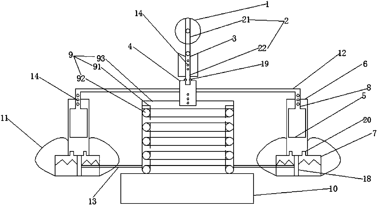
[0034] Such as figure 1 As shown, a spring testing device according to a preferred embodiment of the present invention includes a driving module, a hydraulic circuit module and a loaded force receiving module. Force module connection. The spring testing device of the present invention drives the hydraulic circuit module under the drive of the driving module, so that the spring can simulate the actual working conditions to load the spring in the axial direction under the action of the loading force module, and test the strength of its stiffness and longevity.

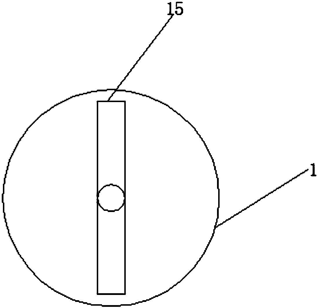
[0035] Specifically, the drive module includes a turntable 1, a push rod 2, a fixed stand 3 and a connecting block 4, the upper end of the push rod 2 is connected with the turntable 1, the lower end of the push rod 2 is connected with the fixed stand 3, and the bottom end of the push rod 2 Connected to connection block 4.

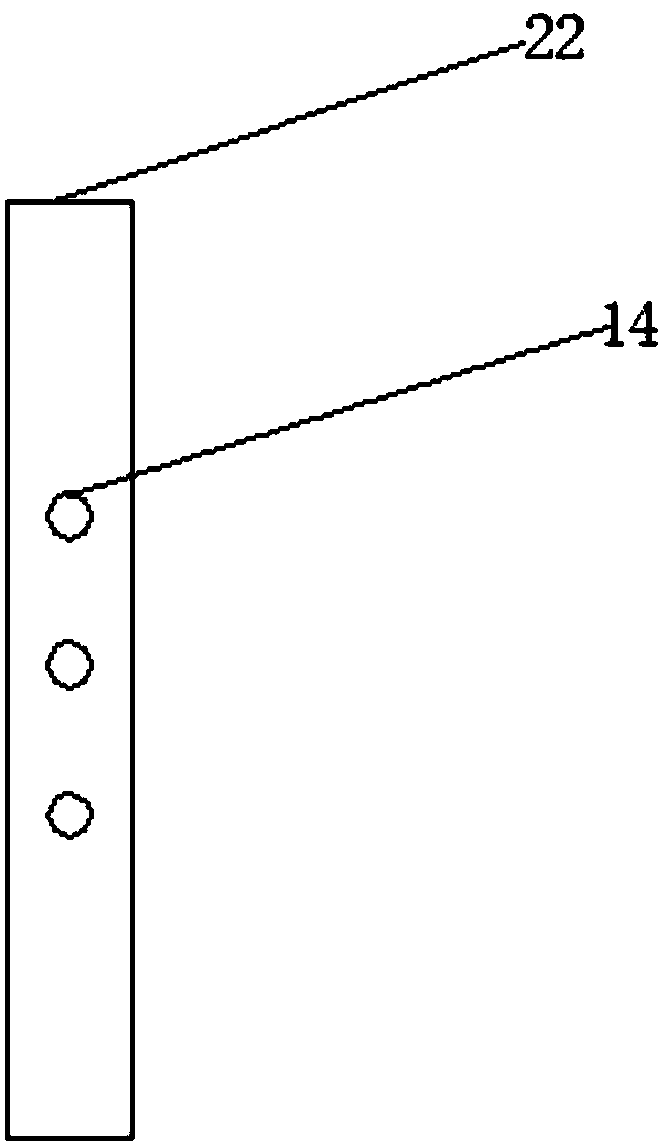
[0036] Such as figure 2 As shown, the push rod 2 includes an upper push rod 21 and a lower pu...


PUM


Abstract

The invention discloses a spring test device, which comprises a driving module, a hydraulic loop module and a loading stress module. The driving module is connected with the hydraulic loop module through a connecting rod; and the hydraulic loop module is connected with the loading stress module through a stretching rod. The hydraulic loop module is driven by the driving module, and thus a spring realizes a purpose of spring quality and life test under the function of the loading stress module.

Description

technical field [0001] The invention relates to the technical field of spring testing, in particular to a spring testing device. Background technique [0002] As a mechanical part that uses elasticity to work, a spring needs to pass strict tests before it can be put into use after it is produced. Because most of the springs are the main components used in machinery and vehicles. If the springs installed on the vehicle have not been strictly tested, but are installed on the vehicle at random, if the performance does not meet the requirements, it will inevitably cause very serious consequences. . The springs used for shock absorbers, because of the decline in their performance, make the vehicle lose its balance and are prone to traffic accidents. [0003] With the development of modern industry, various springs are playing an increasingly important role in various fields. The quality of the spring has greatly affected the overall quality of industrial and agricultural produ...

Claims


Application Information

Patent Timeline
Patent Type & Authority Applications(China)
IPC IPC(8): G01M13/00G01M5/00
CPCG01M5/0075G01M13/00
Inventor 屈盛官尹联民赖福强李小强
Owner SOUTH CHINA UNIV OF TECH
Why Eureka
Try Eureka