Electrohydraulic energy-regenerative type shock absorber

A technology of shock absorbers and accumulators, applied in the directions of liquid shock absorbers, electric components, electromechanical devices, etc., can solve the problems of low efficiency of the energy feeding system, inability to apply to practical applications, shortening the life of generators, etc. The effect of energy recovery efficiency, fewer parts, and simple structure

Active Publication Date: 2010-06-23
武汉经开科创运营有限公司
View PDF4 Cites 58 Cited by
  • Summary
  • Abstract
  • Description
  • Claims
  • Application Information

AI Technical Summary

Problems solved by technology

The disadvantage of the energy recovery system that uses mechanical devices such as rack and pinion or ball screw to convert linear motion into rotation is that it is affected by the internal clearance of the transmission system, and the frequency response function of the system to high-frequency signals is not zero.
For example, when the ball screw type is in the low frequency range and the ground excitation amplitude is large, its energy recovery efficiency and suspension characteristics are better; but when the system frequency is high, its suspension characteristics are not as good as passive suspensions, and energy cannot be recovered. lead to lower overall system efficiency
[0007] In the above technology of converting linear motion into rotation, the motor and the transmission system are connected in a solid state, which causes the motor to continuously change the rotation direction and repeat the motor speed from 0->acceleration->deceleration->motor speed 0 as the system vibrates cycle, creating a large "inertia loss"
This will not only greatly shorten the life of the generator, but also make the generator have little or no time to generate electricity during the entire vibration process, resulting in low efficiency of the entire energy feeding system, so that it cannot be applied to practical applications

Method used


Image

  • Electrohydraulic energy-regenerative type shock absorber
  • Electrohydraulic energy-regenerative type shock absorber
  • Electrohydraulic energy-regenerative type shock absorber

Examples


Embodiment Construction

[0021] The present invention will be further described below in conjunction with the accompanying drawings and specific embodiments.

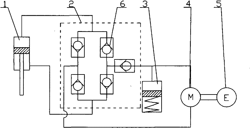
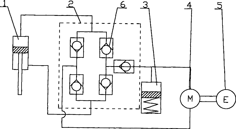
[0022] The invention provides a hydraulic-electric energy-fed shock absorber applied in the technical field of vehicles. It adopts an electromechanical-hydraulic hybrid system, and its working principle is to convert the relative linear motion of the sprung mass and the unsprung mass caused by the unevenness of the ground into a direction-invariant hydraulic flow to drive the hydraulic motor to rotate through the hydraulic rectifier bridge. The hydraulic motor drives the generator to generate electricity, so that the vibration mechanical energy is converted into electrical energy for recovery. Its basic structure is as figure 1 As shown: it mainly includes piston 1, hydraulic rectifier bridge 2, accumulator 3, hydraulic motor 4 and rotary generator 5. When the car vibrates, the piston converts mechanical energy into hydraulic energy by doing ...


PUM


Abstract

The invention relates to an electrohydraulic energy-regenerative type shock absorber, which comprises a hydraulic circuit, a working chamber and a piston, wherein the working chamber is divided into a piston working cavity and an accumulating power-generating cavity by a partition plate (13), and the piston is positioned in the piston working cavity and is connected with an external upper mounting base (7) through a piston push rod (8); a hydraulic motor (4) is positioned in the energy storage power-generating cavity and is connected with an external rotary generator (5) through a driving shaft, and an accumulator (3) is positioned in the accumulating power-generating cavity and is positioned below the partition plate (13); and the hydraulic circuit and a plurality of one-way valves (6) form a hydraulic rectifier bridge, and the hydraulic circuit adopts the method that an external pipeline is arranged outside the piston or the piston is designed to form internal and external cavities. The invention has simple structure, fewer components and small volume, can allow the energy generated by vehicle vibration to be fully used for doing work, can effectively recover vibration energy, has better shock absorbing effect than the existing shock absorber, and also prolongs the service life of the generator.

Description

technical field [0001] The invention relates to a shock absorber, in particular to a hydraulic-electric energy-feeding shock absorber for a vehicle suspension system, which has the function of recovering a part of the vibration energy and can also be used as an actuator to realize the active movement of the suspension system. or semi-active control. Background technique [0002] When the vehicle is running on the road, the bumps of the road and the acceleration and deceleration of the vehicle, steering and other operations will cause relative vibration between the sprung mass and the unsprung mass, and the shock absorber converts this part of mechanical energy into heat energy consumption in the form of friction Dissipate, thereby attenuating the vibration of the vehicle. If these energies can be recycled, the energy consumption of vehicles can be reduced, thereby achieving the purpose of saving energy. The present invention is just based on such an idea, that is, replacin...

Claims


Application Information

Patent Timeline
Patent Type & Authority Applications(China)
IPC IPC(8): F16F9/16F03C1/00H02K7/18
Inventor 过学迅徐琳吴昊天张成才
Owner 武汉经开科创运营有限公司
Why Eureka
Try Eureka