Hydraulic circuit control device

a control device and hydraulic circuit technology, applied in the direction of auxillary lubrication, fluid gearings, machines/engines, etc., can solve the problems of high power consumption and step out of the electric motor, and achieve the effects of low manufacturing cost, high flow rate, and reduced weight and size of the apparatus

Inactive Publication Date: 2006-10-05
HONDA MOTOR CO LTD
View PDF2 Cites 59 Cited by
  • Summary
  • Abstract
  • Description
  • Claims
  • Application Information

AI Technical Summary

Benefits of technology

[0013] The present invention has as its object providing a control unit for a hydraulic circuit that can effectively use a common oil pump for an oil passage that requires a high pressure and an oil passage that requires a low pressure and high flow rate without causing problems such as step out and increased power consumption of the pump driving electric motor.
[0019] When the hydraulic clutch is performing an engagement or disengagement operation, large fluctuations in the hydraulic load occur. However, when supplying oil to the clutch side, since the second electric motor is controlled in the torque control mode, the second electric motor is hardly affected by the hydraulic load. When supplying oil to the cooling portion of the first electric motor or the lubricating portion of the power transmission system, since the second electric motor is controlled in the speed control mode, overspeed of the second electric motor is prevented.
[0021] In this case, when the viscosity of the oil increases at low temperatures, causing the pressure in the second oil passage to be equal to or greater than the first predetermined value, the relief valve discharges the oil in the second oil passage to the drain passage. Because of this, when the second electric motor is operating in speed control mode, an excessive load caused by the change in viscosity of the oil no longer acts on the second electric motor. Therefore, the energy efficiency of the second electric motor can be raised and step loss can be prevented in the second electric motor that is speed controlled.
[0027] In this case, when the pressure at the branch portion side rises to the second predetermined value as oil discharged from the oil pump is supplied to the second oil passage side, the valve body opens the cooling oil passage to supply oil to the cooling portion of the first electric motor, with the supply pressure on the lubricating oil passage side then decreasing. When the pressure at the branch portion side rises to be equal to or greater than the first predetermined value, the valve body opens the drain passage to discharge oil in the second oil passage, and so thereby the pressure in the second oil passage is held lower than the first predetermined value. Accordingly, limiting the pressure of the lubricating oil passage under ordinary use conditions and relief of the oil when the oil viscosity rises can be performed by a single valve body. This can lower manufacturing costs and reduce the weight and size of the apparatus.
[0028] According to this invention, when supplying oil to the first oil passage that requires a high pressure, the second electric motor is controlled in the torque control mode, and when oil is supplied to the second oil passage that requires a low pressure and high flow rate, the second electric motor is controlled in a speed control mode. Therefore, a common oil pump can be effectively used without causing problems such as step out of the second electric motor and increased power consumption of the second electric motor.

Problems solved by technology

However, in the case of always using speed control to control the pump driving electric motor, sudden fluctuations in the hydraulic load when used for the oil passage that requires a high pressure may cause step out of the electric motor.
Controlling the pump driving motor by torque control has also been investigated, but in this case, overspeed of the electric motor occurs when used for the oil passage that requires a low pressure and a high flow rate, leading to high power consumption, which is not desirable from the standpoint of energy conservation.

Method used


Image

  • Hydraulic circuit control device
  • Hydraulic circuit control device
  • Hydraulic circuit control device

Examples


Embodiment Construction

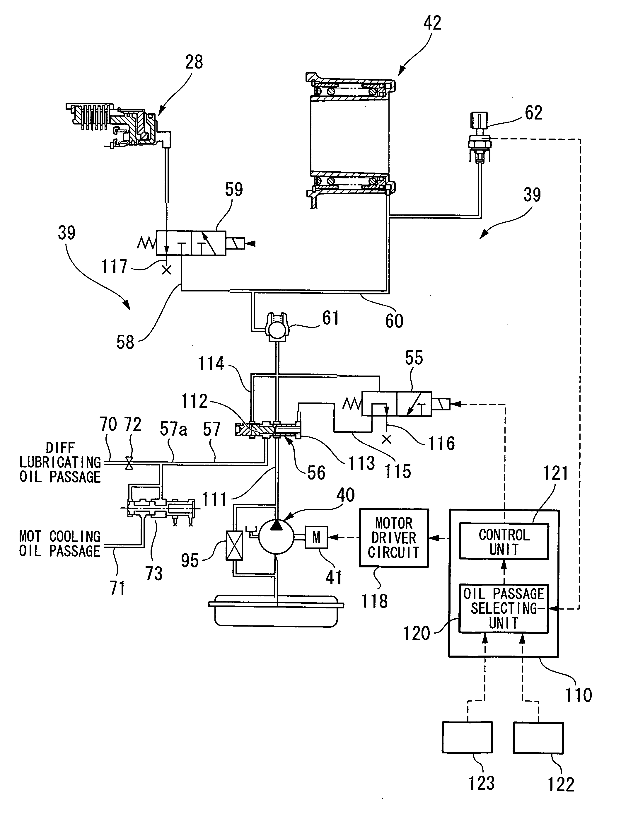
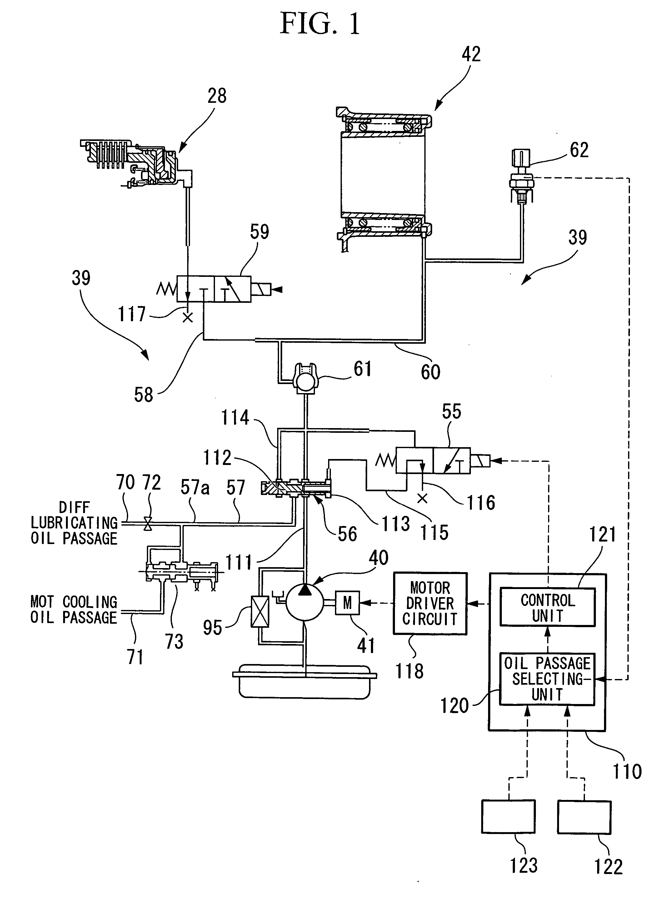
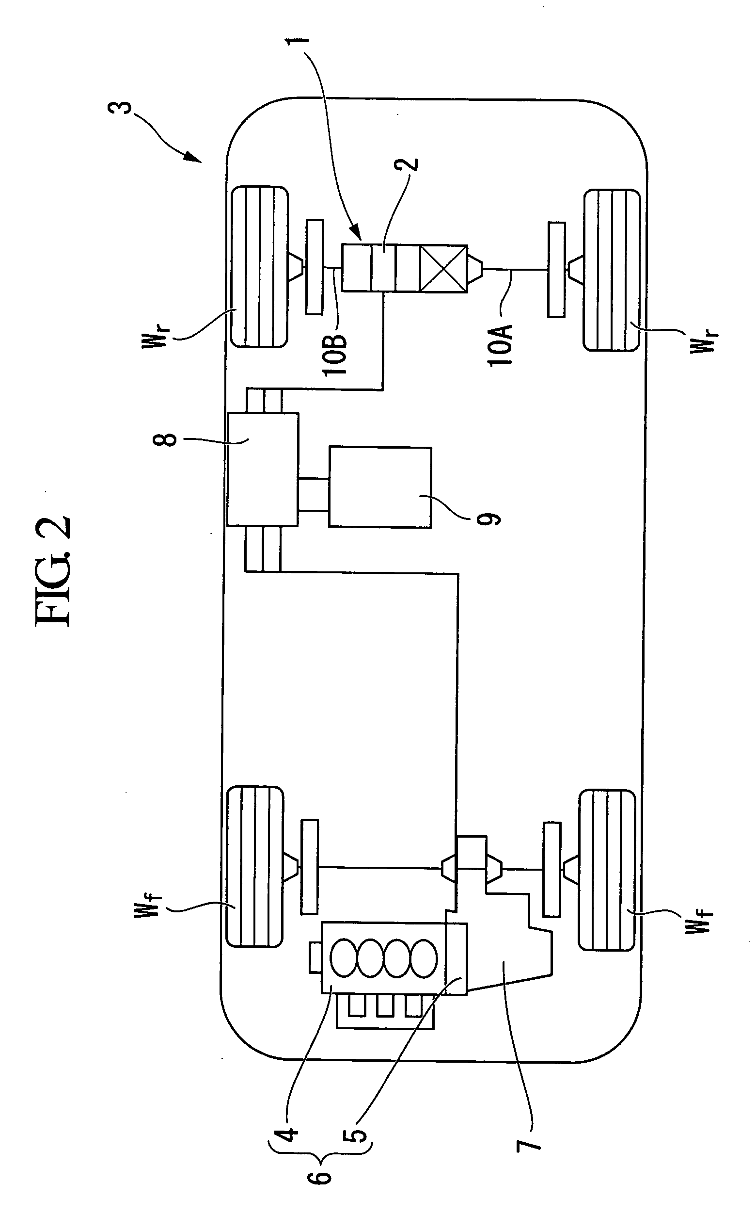
[0041] The embodiment of the present invention is described below with reference to the accompanying drawings. This embodiment applies the hydraulic circuit control device according to the present invention to a hydraulic system provided in a drive device 1 for auxiliary drive use in a vehicle 3 shown in FIG. 2.

[0042] The entire constitution of the vehicle shown in FIG. 2 and the drive device 1 shown in FIGS. 3 and 4 shall initially be described. The vehicle 3 shown in FIG. 2 is a hybrid vehicle having a drive unit 6 in which an internal combustion engine 4 and an electric motor 5 are connected in series. The drive power of the drive unit 6 is transmitted to front wheels Wf via a transmission 7, and the drive power of a drive device 1 for auxiliary driving provided separate to the drive unit 6 is transmitted to rear wheels Wr. The drive device 1 is driven by an electric motor 2 (wheel driving electric motor). The electric motor 5 of the drive unit 6 and the electric motor 2 of the ...


PUM


Abstract

A hydraulic circuit control device that selectively supplies oil to a first oil passage and a second oil passage by an oil pump, the control device includes: an oil passage switching unit adapted to connect the oil pump to either the first oil passage or the second oil passage; a control mode switching unit adapted to switch the control mode of the electric motor to either a torque control mode or a speed control mode; an oil passage selecting unit adapted to select whether to connect the oil pump to the first oil passage or the second oil passage; and a control unit adapted to perform control so that the control mode switching unit switches the control mode to the torque control mode when the first oil passage has been selected, and perform control so that the control mode switching unit switches the control mode to the speed control mode when the second oil passage has been selected.

Description

BACKGROUND OF THE INVENTION [0001] 1. Field of the Invention [0002] The present invention relates to a hydraulic circuit control device that selectively supplies oil to two oil passages with an oil pump. [0003] Priority is claimed on Japanese Patent Application No. 2005-102507, filed Mar. 31, 2005, and Japanese Patent Application No. 2005-336782, filed Nov. 22, 2005, the contents of which are incorporated herein by reference. [0004] 2. Description of Related Art [0005] A vehicle drive system has been developed in which either the front or rear wheels are powered by a main drive source such as an internal combustion engine, while an auxiliary drive source is provided by an electric motor for the other wheels. [0006] Under normal driving conditions in a vehicle equipped with such a drive system, the main drive source drives the front or rear wheels, while the auxiliary drive source is activated to transmit drive power to the other wheels when, for example, setting off in adverse road ...

Claims


Application Information

Patent Timeline
Patent Type & Authority Applications(United States)
IPC IPC(8): F16H61/14F01P3/00F01M1/02B60K17/356F04B49/06F15B11/00F15B21/14F16H57/04
CPCB60K6/387Y10T477/73B60K6/48B60K6/52B60K17/356B60K2001/001B60W10/02B60W10/08B60W20/00F01P2003/006F16H57/0441F16H57/0476F16H61/0021F16H2061/0037Y02T10/6221Y02T10/623Y02T10/6265Y10T477/69398Y10T477/693962Y10T477/693625B60K6/44Y02T10/62B60W20/15
Inventor NISHIKAWA, RYOAOKI, TAKASHITANAKA, MASASHIKIRA, NOBUHIRO
Owner HONDA MOTOR CO LTD
Why Eureka
Try Eureka