

Hydraulic energy intensifier
a technology of hydraulic energy intensifier and energy recovery circuit, which is applied in the direction of fluid couplings, couplings, mechanical equipment, etc., to achieve the effect of increasing the amount of hydraulic energy stored, lowering the energy load, and increasing the energy of the hydraulic pump
- Summary
- Abstract
- Description
- Claims
- Application Information
AI Technical Summary
Benefits of technology
Problems solved by technology
Method used
Image

Examples
Embodiment Construction
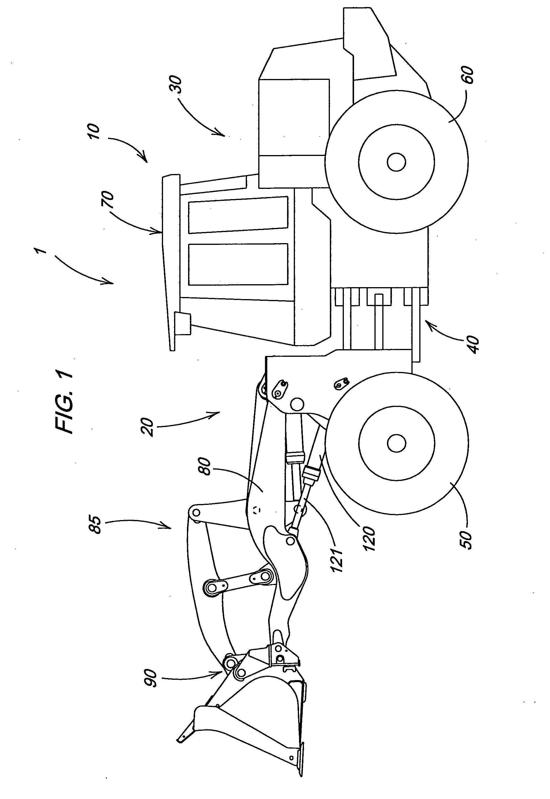
[0010]FIG. 1 illustrates a work vehicle in which the invention may be used. The particular work vehicle illustrated in FIG. 1 is an articulated four wheel drive loader 1 having a main vehicle body 10 that includes a front vehicle portion 20 pivotally connected to a rear vehicle portion 30 by vertical pivots 40, the loader being steered by pivoting of the front vehicle portion 20 relative to the rear vehicle portion 30 in a manner well known in the art. The front and rear vehicle portions 20 and 30 are respectively supported on front drive wheels 50 and rear drive wheels 60. An operator's station 70 is provided on the rear vehicle portion 30 and is generally located above the vertical pivots 40. The front vehicle portion 20 includes a boom 80, a linkage assembly 85, a work tool 90 and a hydraulic cylinder 120. The front and rear drive wheels 50 and 60 propel the vehicle along the ground and are powered in a manner well known in the art.
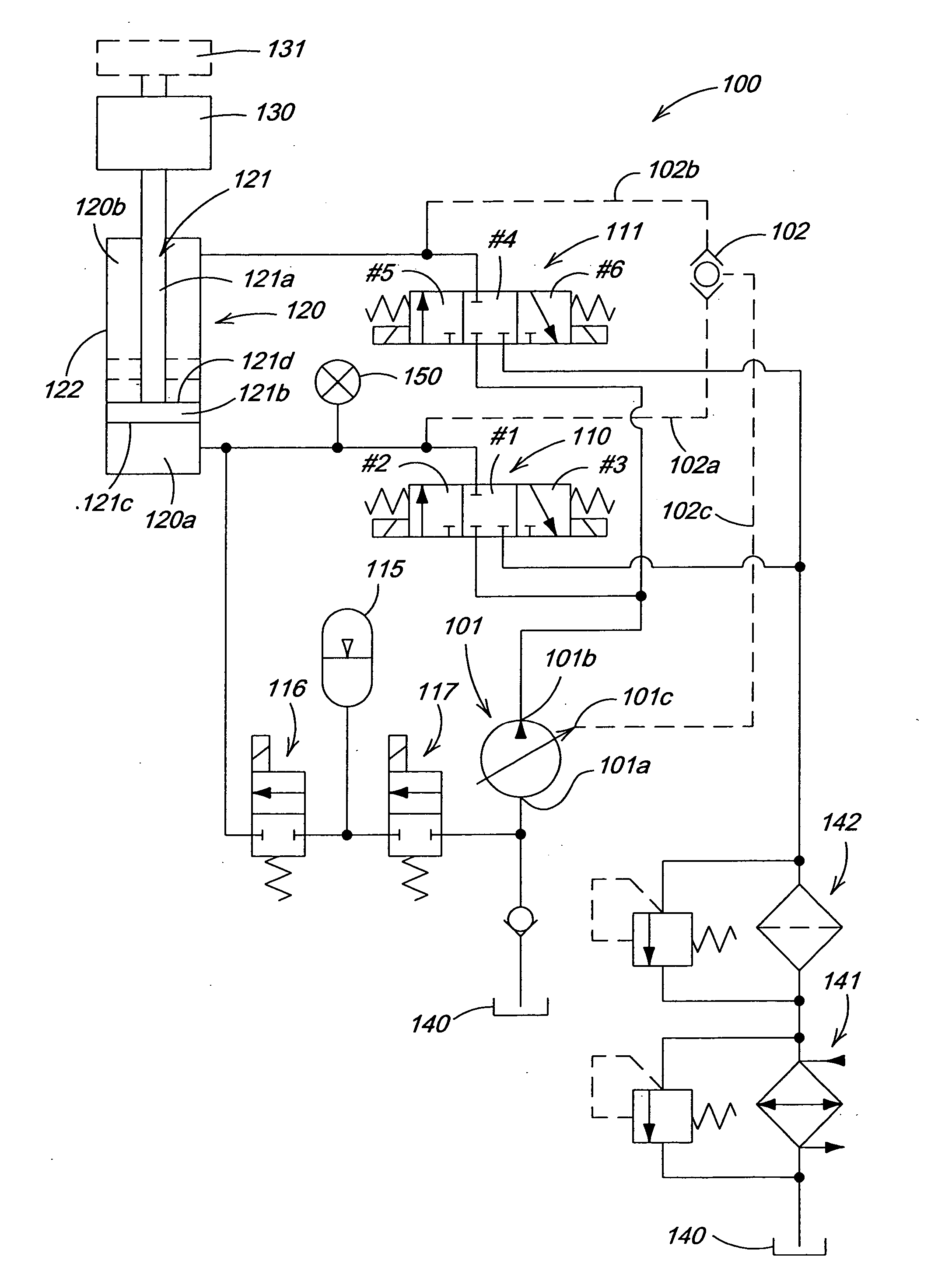
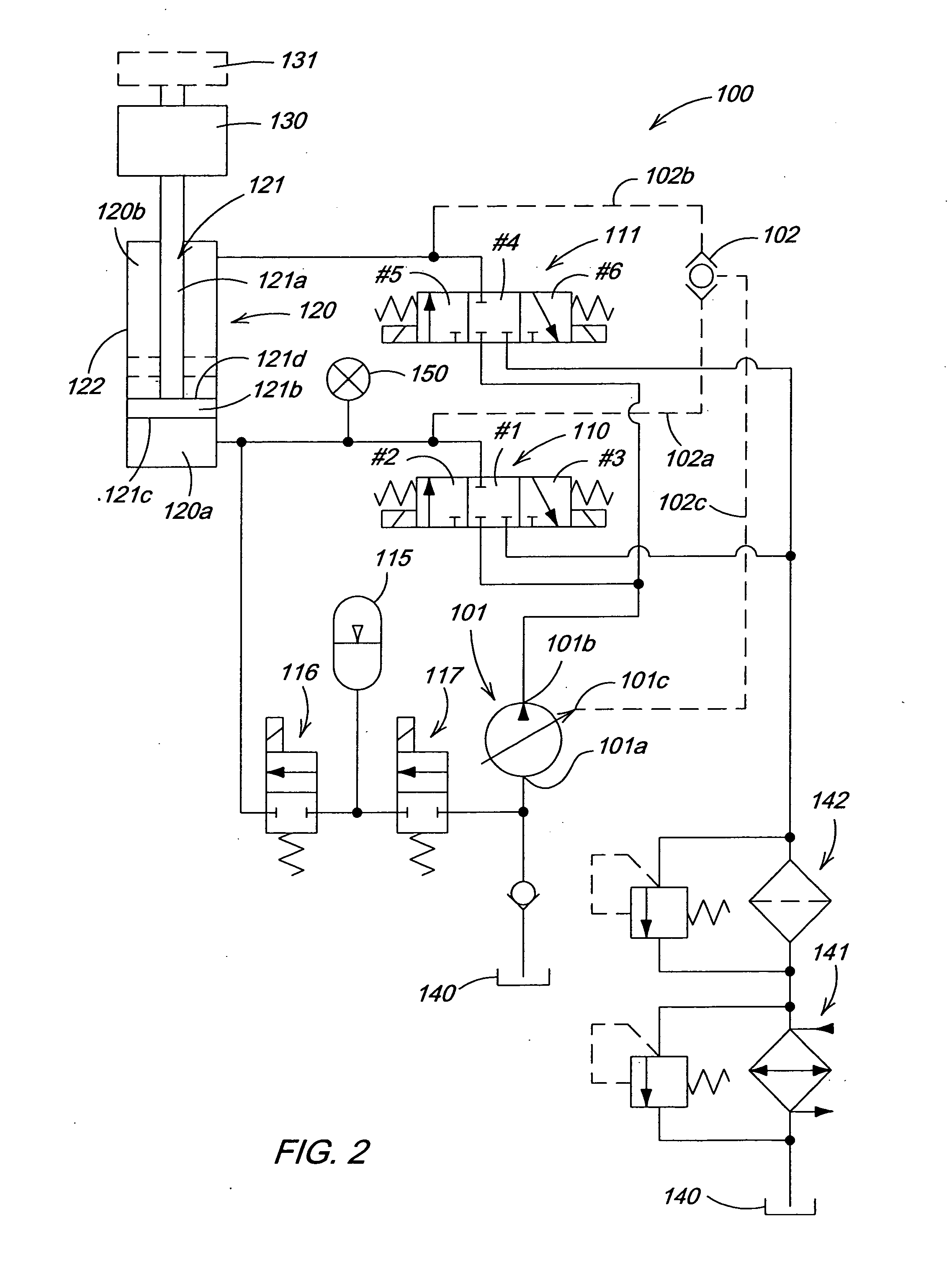
[0011]FIG. 2 illustrates a hydraulic circuit 10...
PUM
 Abstract
Description
Claims
Application Information