Room ventilating control method based on air exhaust type fresh air ventilator

A control method and technology for fresh air fans, applied in heating and ventilation control systems, space heating and ventilation, ventilation layout, etc., can solve the problem that the indoor environment control effect is far inferior, the perspective and lighting effects are worse, and the glass cavity is difficult to clean. and other problems, to achieve the effect of reducing thermal discomfort, prolonging residence time, and reducing heating load

Active Publication Date: 2020-05-29
CHONGQING UNIV
View PDF11 Cites 1 Cited by
  • Summary
  • Abstract
  • Description
  • Claims
  • Application Information

AI Technical Summary

Problems solved by technology

In this patent, it seems that various functions such as air purification, temperature adjustment, and humidity adjustment are set on the windows, which improves the functionality of the windows, but in fact, the glass windows have their own functions of lighting inside the house and seeing through the outside, as well as the installation location, Restricted by size and other requirements, it is not suitable to directly integrate functions such as air purification, temperature adju...

Method used


Image

  • Room ventilating control method based on air exhaust type fresh air ventilator
  • Room ventilating control method based on air exhaust type fresh air ventilator
  • Room ventilating control method based on air exhaust type fresh air ventilator

Examples


Embodiment Construction

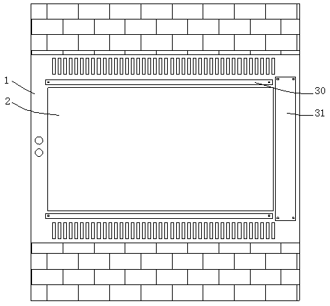
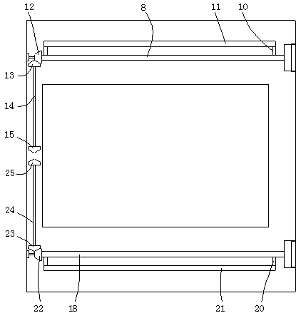
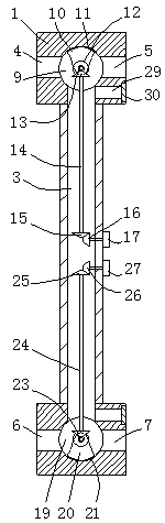
[0072] The present invention will be further described in detail below in combination with specific embodiments. Figure 8-10 A simplified schematic diagram of the glass window structure in , and the arrows in the figure indicate the direction of wind flow.

[0073] In specific implementation: a room ventilation control method based on exhaust-type fresh air fans, air-conditioning equipment and exhaust-type fresh air fans are pre-installed in the room, and glass windows with ventilation functions are used for room windows. A ventilated inner cavity is formed between the layers of glass, characterized in that the room is ventilated according to the following operating control modes;

[0074] 1) Indoor cooling and ventilation mode when solar radiation is weak in summer, (see Figure 8 ) At this time, the air conditioner is cooling, the indoor air temperature is lower than the glass window temperature is lower than the outdoor temperature (this is used as a way to judge the inte...


PUM


Abstract

The invention discloses a room ventilating control method based on an air exhaust type fresh air ventilator. Air conditioning equipment, the air exhaust type fresh air ventilator and a glass window with a ventilating function are pre-mounted in a room, and room ventilation is realized according to the following operation control modes: 1) an indoor refrigerating ventilating mode while solar radiation in summer is weak, wherein outdoor air is controlled to flow through a glass sandwiched ventilating inner cavity from an upper outer side air flue, and then flows out from a lower inner side air flue; 2) an indoor refrigerating ventilating mode while solar radiation in summer is strong, wherein outdoor air enters from a lower outer side air flue, one part of air upwards passes through a ventilating inner cavity and then flows out from the upper outer side air flue, and the other part of air directly enters the room from the lower inner side air flue; and 3) a winter indoor heating ventilating mode, wherein outdoor air is controlled to enter from the lower outer side air flue, upwards flows through the ventilating inner cavity, and then flows into the room from the upper inner side airflue. The room ventilating control method can improve indoor thermal insulation and heat insulation property better, reduces room temperature-control energy load, and saves consumption.

Description

technical field [0001] The invention belongs to the technical field of building room ventilation, and in particular relates to a room ventilation control method based on an exhaust-type fresh air fan. Background technique [0002] With the improvement of people's material living standards, people have higher and higher requirements for the comfort of residential houses. Many high-end residential houses will install a fresh air system to regulate the temperature and ventilation in the house. At the same time, according to the latest national standard for civil building heating, ventilation and air conditioning design, it is clearly stipulated that all rooms in civil buildings need to consider the ventilation design requirements of a certain amount of fresh air, but at the same time, because this action will bring untreated outdoor air into the room and The air stagnated in the room is exhausted to the outside, so that the air conditioner must additionally undertake the work ...

Claims


Application Information

Patent Timeline
IPC IPC(8): F24F11/46F24F11/65F24F11/72F24F11/80E06B7/02E06B7/28A47L1/12
CPCA47L1/12E06B7/02E06B7/28F24F11/46F24F11/65F24F11/72F24F11/80
Inventor 陈金华段超凡路立地唐茂川谢文进刘志龙
Owner CHONGQING UNIV
Why Eureka
Try Eureka