
Particle concentrator

A concentration device and particle technology, applied in the direction of measuring devices, dispersed particle separation, particle size analysis, etc., can solve problems such as difficulty in concentration, unsuitability, and difficulty in nano-aerosol concentration

Inactive Publication Date: 2018-03-16
SHIMADZU SEISAKUSHO CO LTD
View PDF3 Cites 2 Cited by
  • Summary
  • Abstract
  • Description
  • Claims
  • Application Information

AI Technical Summary

Problems solved by technology

Therefore, the above-mentioned concentrator is not suitable for the case where it is desired to measure the particle size distribution of the aerosol in the gas.
In addition, the smaller the particles that cannot obtain enough inertia, the easier it is to flow with the flow of a large flow of gas, so it is difficult to concentrate the small particles
In fact, even if a normal virtual impactor as described in Non-Patent Document 1 is used, it can only concentrate particles with a size above the submicron level, and it is difficult to concentrate nano-aerosols.

Method used


Image

  • Particle concentrator
  • Particle concentrator
  • Particle concentrator

Examples


no. 1 Embodiment

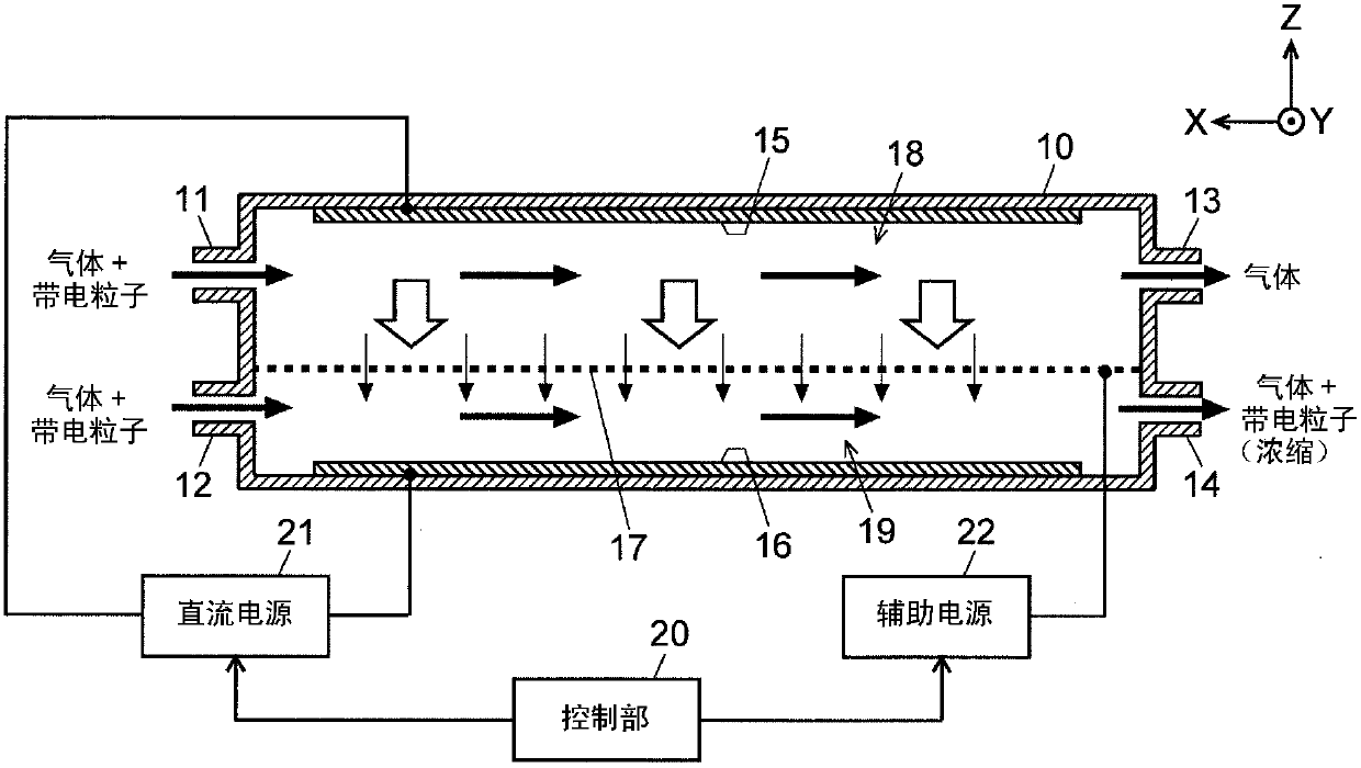
[0042] Below, refer to figure 1 The particle concentrator of the first embodiment of the present invention will be described. figure 1 It is a longitudinal sectional view showing a schematic structure of the particle concentrator of this embodiment.

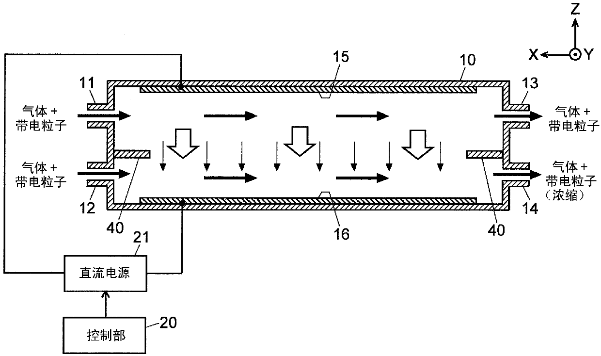
[0043] In addition, for the convenience of explanation, the figure 1 The X direction in is set to the left, the Y direction is set to the front, and the Z direction is set to the top, thereby defining front and rear, up and down, and left and right. This is described later figure 2 , image 3 and Figure 6 is also the same.

[0044] The particle concentrating device of the first embodiment has a substantially rectangular parallelepiped housing 10, and first openings serving as openings for letting gas flow into the housing 10 from the outside are arranged along the left side of the housing 10 along the vertical direction. A gas introduction port (corresponding to the gas introduction part in the present invention) 11 an...

no. 2 Embodiment

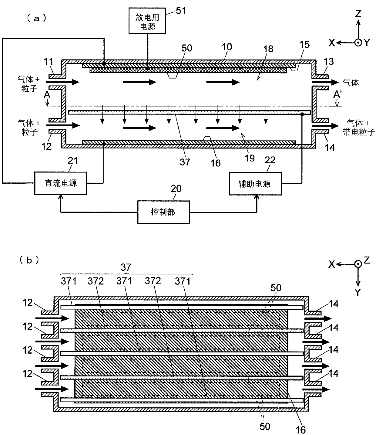
[0059] Next, refer to image 3 and Figure 4 A particle concentrator according to a second embodiment of the present invention will be described. image 3 (a) is a longitudinal sectional view showing a schematic structure of the particle concentrator of the second embodiment, image 3 (b) is image 3 A-A' line sectional view in (a). Figure 4 It is a perspective view of the filter 37 in the particle concentrator of the second embodiment. Also, yes image 3 , Figure 4 Components that are the same as or equivalent to those of the device of the first embodiment are given the same reference numerals as those of the first embodiment.

[0060] In the particle concentrating device of the first embodiment described above, the carrier gas containing the particles charged outside the case 10 is supplied into the housing 10, but in the particle concentrating device of the second embodiment, at least through the first The gas inlet 11 supplies carrier gas containing uncharged unch...


PUM


Abstract

A gas stream containing charged particles is introduced through a first gas inlet port (11) into a first space (18), while another gas stream containing charged particles is introduced through a second gas inlet port (12) into a second space (19) located below and separated from the first space by a mesh-like filter (17). Voltages are respectively applied to an upper plate electrode (15), lower plate electrode (16) and filter (17) to create a DC electric field within a housing (10). Due to this electric field, the charged particles contained in the gas stream flowing in the first space (18) move toward the second space (19). The charged particles which have entered the second space (2) through the openings of the filter (17) are extracted through a gas outlet port (18) along with the charged particles originally contained in the gas stream flowing in the second space (19).

Description

technical field [0001] The present invention relates to a particle concentration device for increasing the density (number of particles per unit volume) of particles in gas. Background technique [0002] Tiny liquid or solid particles floating in gas are called aerosols. Most of the pollutants in automobile exhaust and soot from factories are also aerosols, and there have been concerns about the health effects of so-called nano aerosols, especially those with a particle size of less than 1 μm. Under such circumstances, the measurement of the particle size and the measurement of the particle size distribution are very important in fields such as environmental measurement and evaluation. As a device for measuring the particle size distribution of aerosol, a differential electric mobility measuring device (DMA= Differential Mobility Analyzer). [0003] When the density of the aerosol contained in the gas to be measured is low, it is necessary to concentrate the aerosol in or...

Claims


Application Information

Patent Timeline
Patent Type & Authority Applications(China)
IPC IPC(8): H01T23/00G01N15/02
CPCG01N15/02H01T23/00G01N1/40G01N2001/4038B03C3/47B03C3/41G01N2015/0038G01N15/0266B03C3/0175G01N1/2205B01D53/32
Inventor 关洋上野良弘奥田浩史樱井博
Owner SHIMADZU SEISAKUSHO CO LTD
Learn More