
Item of jewelery

A technology of jewelry and jewelry, applied in the field of jewelry

Inactive Publication Date: 2018-03-16
GEBR SCHAFFRATH
View PDF5 Cites 0 Cited by
  • Summary
  • Abstract
  • Description
  • Claims
  • Application Information

AI Technical Summary

Problems solved by technology

[0004] Known pieces of jewelry with movable jewelry elements have the disadvantage that in the area of ​​the upper side of the jewelry element, that region with particularly high light reflection properties is often just covered by the blocking element

Method used


Image

  • Item of jewelery
  • Item of jewelery
  • Item of jewelery

Examples


Embodiment Construction

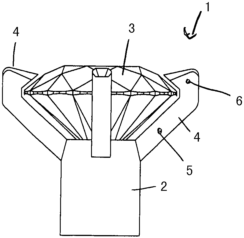
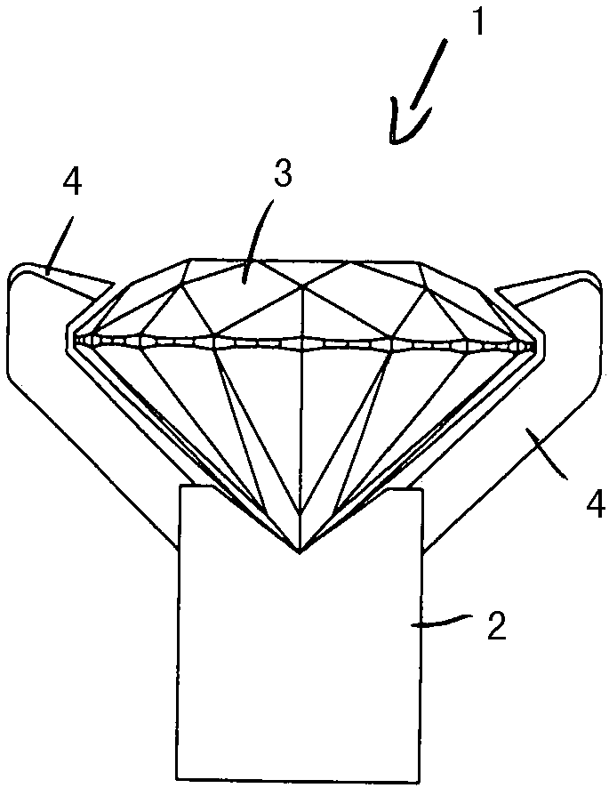
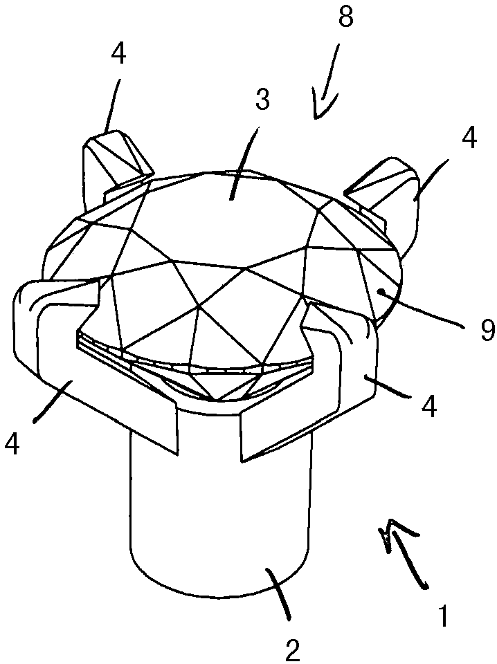
[0043] figure 1 Shown is a jewelry piece (1) with a base element (2) and a jewelry element (3) guided movably in the base element (2). according to figure 1 In the embodiment, the jewelry element (3) is prevented from falling out of the base element (2) by the blocking element (4). Three of the four blocking elements (4) are in figure 1 visible in . according to figure 1 The blocking element (4) has a hook-shaped structure. Starting from the base element (2), first a connecting strip (5) extends, which then transitions into a stop strip (6). The stop strip (6) protrudes above the jewelry element (3) in the edge region of the jewelry element (3). The center ( 7 ) of the jewelry element ( 3 ) is thus visually freely visible.

[0044] In the exemplary embodiment shown, the jewelry element ( 3 ) is designed as a diamond, which has a plurality of facets ( 9 ) in the region of the upper side ( 8 ).

[0045] according to figure 2 In a modified embodiment of , two blocking e...


PUM


Abstract

The invention relates to an item of jewelery (1) comprising a base element (2) and at least one gem (3) which is mounted so that it can be moved in the base element (2) such that the gem (3) can movewith respect to the base element (2). Said gem (3) is arranged, at least in areas, in a recess (13) of the base element (2) and is secured by at least one retaining element (4) to prevent falling outfrom the recess.s, in aSaid retaining element (4) extends from the base element (2) slightly over one part of the upper side of the gem (3) such that the centre of the upper side is not covered by theretaining element (4).

Description

technical field [0001] The invention relates to a piece of jewelry having a base element and at least one jewelry element held movably in the base element such that the jewelry element is held movably relative to the base element, in which piece of jewelry In this case, the jewelry element is arranged at least in regions in a recess of the base element and is prevented from falling out of the recess by at least one blocking element. Background technique [0002] Such pieces of jewelry, in particular with movably held diamonds, are known in various embodiments. Such jewelry is described, for example, in WO 2014 / 082622 A1. The movable diamond there is prevented from falling out by a bow-shaped stop element extending above the diamond. Another prior art is formed by EP 13 36 351 B1. [0003] It is also known to arrange movable diamonds under a transparent disc of jewelry. [0004] Known pieces of jewelry with movable jewelry elements have the disadvantage that in the area o...

Claims


Application Information

Patent Timeline
Patent Type & Authority Applications(China)
IPC IPC(8): A44C7/00A44C9/00A44C17/02
CPCA44C7/003A44C9/00A44C17/0258A44C17/0275
Inventor A·络兹
Owner GEBR SCHAFFRATH
Learn More