Ejector, processing device, and cleaning device

A technology for injectors and cleaning objects, which is applied in the direction of fine working devices, stone processing equipment, manufacturing tools, etc., can solve problems such as increased chip manufacturing costs, reduced attractiveness of injectors, poor processing or cleaning, etc., to reduce defects Affects, inhibits the effect of reducing attractiveness, cheap processing or cleaning

Pending Publication Date: 2022-01-04
DISCO CORP
View PDF2 Cites 0 Cited by
  • Summary
  • Abstract
  • Description
  • Claims
  • Application Information

AI Technical Summary

Problems solved by technology

As a result, the suction force of the ejector decreases, which may cause problems in the processing or cleaning of the processed object
[0014] Although there are also ejectors that reduce the adverse effects of liquid intruding into the interior, such ejectors are large-scale devices with complicated mechanisms and require a large amount of driving fluid.
Therefore, when a chip is manufactured using such an injector, there may be a problem that the manufacturing cost of the chip increases.

Method used


Image

  • Ejector, processing device, and cleaning device
  • Ejector, processing device, and cleaning device
  • Ejector, processing device, and cleaning device

Examples


Embodiment Construction

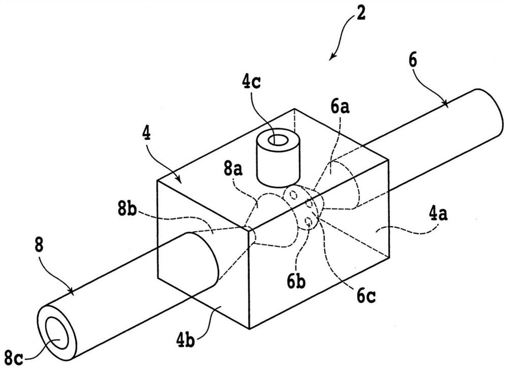
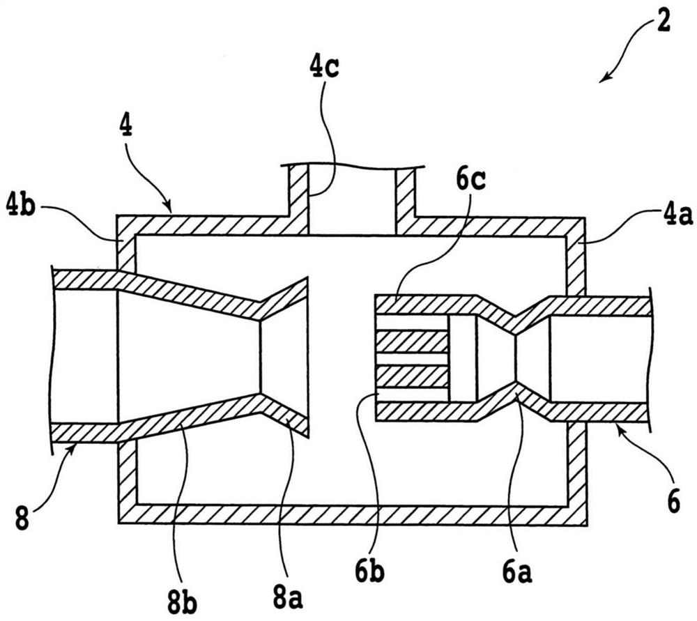
[0033] Embodiments of the injector will be described with reference to the drawings. figure 1 is a perspective view schematically showing the injector 2 of the embodiment, figure 2 is schematically shown figure 1 A cross-sectional view of a portion of injector 2 is shown.

[0034] The injector 2 generates an attractive force by causing a driving fluid to flow inside the main body portion 4 isolated from the outside. The driving fluid may be either liquid or gas. The driving fluid is, for example, a liquid such as water, or a gas such as air or an inert gas such as argon or nitrogen.

[0035] The main body part 4 has mutually opposing walls 4a and 4b, and the suction path 4c provided in the wall of the main body part 4 other than the walls 4a and 4b. Furthermore, one end side of the inflow pipe 6 is inserted into the wall 4a, and one end side of the outflow pipe 8 is inserted into the wall 4b.

[0036] The inflow pipe 6 provides a path for the driving fluid to flow into t...


PUM


Abstract

The invention provides an ejector, a processing device, and a cleaning device. The ejector can suppress the reduction of suction force when liquid enters the ejector, and can process or clean an object to be processed at low cost. The injector generates the suction force, and is provided with an inflow pipe which has a plurality of openings formed at the front end thereof and from which the driving fluid is injected; an outflow tube having a receiving port for receiving the driving fluid ejected from the opening at a position facing the tip of the inflow tube; and a main body part that surrounds the opening and the receiving port and has a suction path that sucks an external fluid into the interior.

Description

technical field [0001] The present invention relates to an injector for generating suction, and a processing device and a cleaning device having the same. Background technique [0002] Electronic devices such as personal computers and smartphones have chips of semiconductor devices such as IC (Integrated Circuit: Integrated Circuit) and LSI (Large Scale Integration: Large Scale Integration). This chip is manufactured by dividing a wafer having a functional layer formed on the front surface of a semiconductor substrate such as silicon or silicon carbide. [0003] The wafer is divided, for example, by grinding the back surface to a desired thickness and then cutting along planned dividing lines. In addition, processing debris generated during processing may adhere to the wafer and the front surfaces of individual chips manufactured from the wafer, so the wafer and the chips are often cleaned at an appropriate timing. [0004] A processing device for grinding or cutting a waf...

Claims


Application Information

Patent Timeline
Patent Type & Authority Applications(China)
IPC IPC(8): B28D5/00B28D5/02
CPCB28D5/022B28D5/0082B28D5/0058B28D5/0076H01L21/67092H01L21/67051B08B3/02
Inventor 福冈武臣
Owner DISCO CORP
Why Eureka
Try Eureka