Abdominal fitness roller
An abdominal wheel and wheel body technology is applied to training equipment for adjusting cardiovascular system, training equipment for adjusting coordination, gymnastics equipment, etc. and other problems to achieve the effect of increasing difficulty, increasing exercise intensity, and preventing strains
- Summary
- Abstract
- Description
- Claims
- Application Information
AI Technical Summary
Problems solved by technology
Method used
Image
Examples
Embodiment 1
[0029] A detailed description will be given below of specific embodiments of the present invention according to the accompanying drawings.
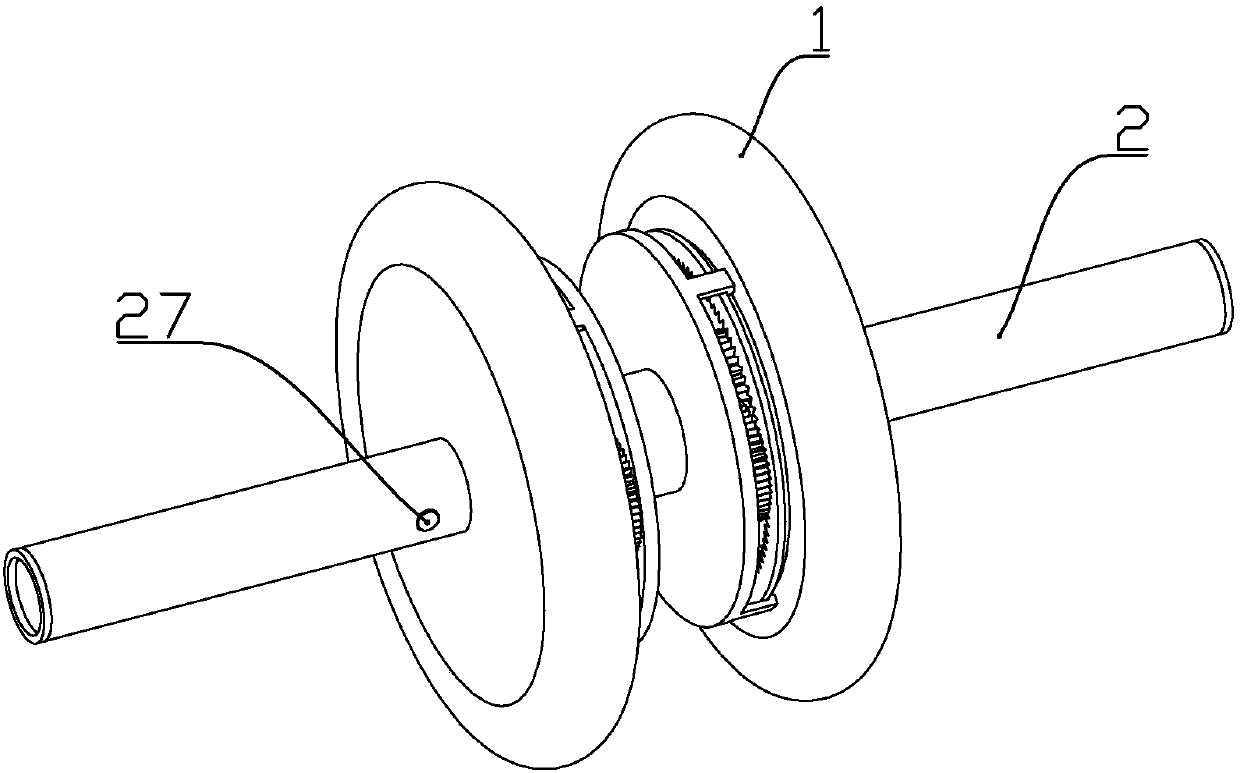
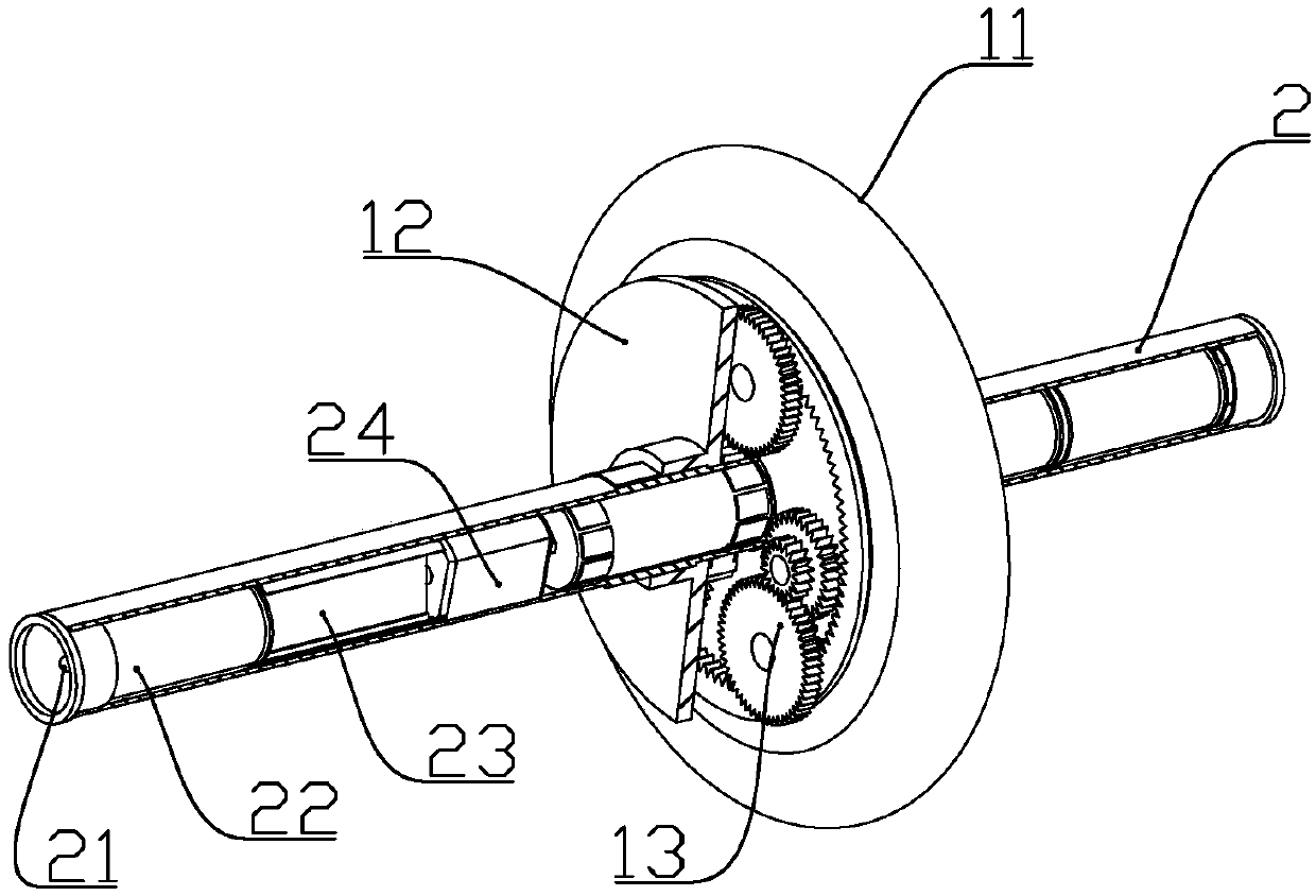
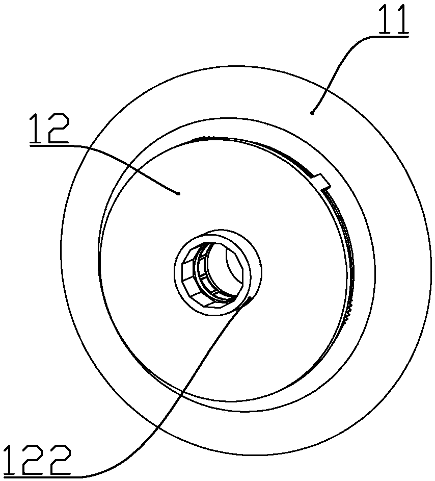
[0030] according to Figure 1-Figure 9 As shown, the abdominal strengthening wheel described in this embodiment includes a support tube 2 made of aluminum alloy and rollers 1 arranged in pairs, and the rollers arranged in pairs are installed on the support tube.
[0031] A polygonal positioning ring 20 is formed at the center of the outer wall of the support tube, a driven rotor 25 is installed at the center of the support tube, magnets b251 are fixedly connected to both ends of the driven rotor, and the driven rotor is located inside the support tube. Motors 24 are fixedly installed at both ends of the rotor, and the output shaft of the motor is connected to the driven rotor in rotation; a circuit board 23 and a battery 22 are also fixedly installed inside the support tube, and the motor and the battery are respectively Electrically con...
Embodiment 2
[0044] according to Figure 1-Figure 6 as well as Figure 10-Figure 12 As shown, the abdominal strengthening wheel described in this embodiment includes a support tube 2 made of aluminum alloy and rollers 1 arranged in pairs, and the rollers arranged in pairs are installed on the support tube.
[0045] A polygonal positioning ring 20 is formed at the center of the outer wall of the support tube, a driven rotor 25 is installed at the center of the support tube, magnets b251 are fixedly connected to both ends of the driven rotor, and the driven rotor is located inside the support tube. Motors 24 are fixedly installed at both ends of the rotor, and the output shaft of the motor is connected to the driven rotor in rotation; a circuit board 23 and a battery 22 are also fixedly installed inside the support tube, and the motor and the battery are respectively Electrically connected to the circuit board.
[0046] One end of the support tube is fixed with a lighting lamp 21, and the ...
Embodiment 3
[0064] This embodiment also includes the following features on the basis of Embodiment 2, the handle 41 includes a spherical handle head and a handle body; the handle body includes a polished rod part and a threaded part, and the polished rod part and the wheel The body is rotated and connected, and is positioned on the wheel body through the crank head and the nut; the other wheel body is provided with a threaded hole on the circumference corresponding to the position of the rocker; when the present invention is used as an abdominal wheel, the threaded part Extend to the threaded hole of another wheel body, and this wheel body is threadedly connected, has reduced the length that described rocking handle stretches out of wheel body like this, reduces the hand that the rocking handle that stretches out when the user uses and acts on the support tube. , At the same time, the two wheel bodies are connected into one body to increase the stability of the structure.
PUM
 Abstract
Description
Claims
Application Information
 - R&D
- Intellectual Property
- Life Sciences
- Materials
- Tech Scout
- Unparalleled Data Quality
- Higher Quality Content
- 60% Fewer Hallucinations
Browse by: Latest US Patents, China's latest patents, Technical Efficacy Thesaurus, Application Domain, Technology Topic, Popular Technical Reports.
© 2025 PatSnap. All rights reserved.Legal|Privacy policy|Modern Slavery Act Transparency Statement|Sitemap|About US| Contact US: help@patsnap.com


