Easy-to-operate power maintenance device

An electrical maintenance and easy-to-operate technology, applied in ladders, buildings, building structures, etc., can solve the problems of heavy load, high risk factor, and inaccessibility of maintenance ladders, and achieve increased working height, good anti-skid effect, and good anti-skid. effect of effect

Pending Publication Date: 2018-03-20
国网新疆电力有限公司和田供电公司 +1
View PDF9 Cites 7 Cited by
  • Summary
  • Abstract
  • Description
  • Claims
  • Application Information

AI Technical Summary

Problems solved by technology

[0002] Ladders are often used during the maintenance and emergency repair of electrical equipment. During the maintenance process, the maintenance ladder needs to be leaned against supports such as walls and poles, and maintenance workers climb up the steps to perform maintenance on the electrical equipment above. In some cases where the ground is slippery, when maintenance workers climb up the maintenance ladder, the maintenance ladder will slip along the lower part of the vertical bar, which will easily cause accidents and bring safety hazards to the maintenance personnel; the existing ladders only have the function of climbing up. When maintenance personnel climb to the top of the ladder for maintenance, they often forget or do not think of bringing certain tools, and they can only rely on the maintenance personnel to climb down to get the tools, which will waste more time, or the people on the ground will climb up to deliver the tools. In this way, when there are two people on the maintenance ladder, the load on the maintenance ladder is relatively large, and its risk factor is relatively large; in addition, maintenance workers generally carry tool boxes when they climb up the maintenance ladder for maintenance, and there is nowhere to store the tool boxes above the maintenance ladder , causing more trouble; at the same time, the length of the ladder will be limited, and some higher places cannot be reached

Method used


Image

  • Easy-to-operate power maintenance device
  • Easy-to-operate power maintenance device
  • Easy-to-operate power maintenance device

Examples


Embodiment Construction

[0018] The following will clearly and completely describe the technical solutions in the embodiments of the present invention with reference to the accompanying drawings in the embodiments of the present invention. Obviously, the described embodiments are only some, not all, embodiments of the present invention. Based on the embodiments of the present invention, all other embodiments obtained by persons of ordinary skill in the art without making creative efforts belong to the protection scope of the present invention.

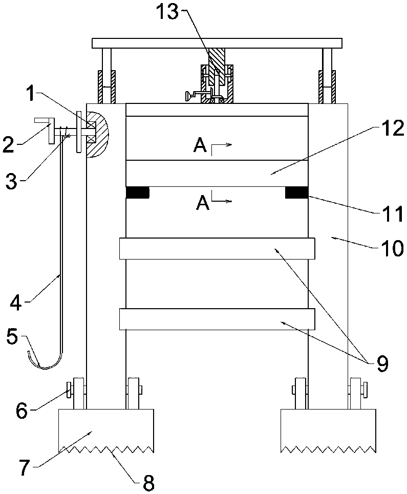
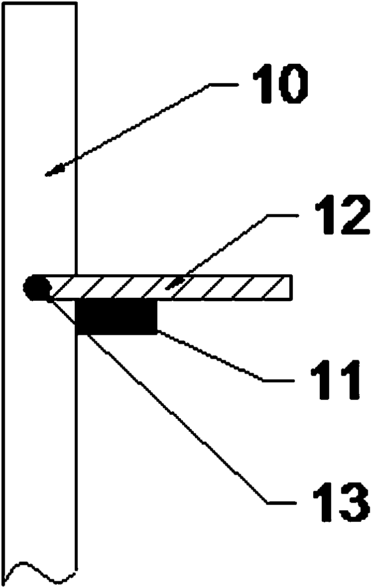
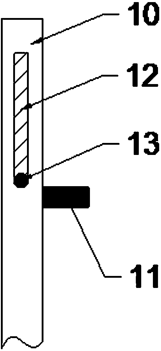
[0019] see Figure 1-Figure 4 , in an embodiment of the present invention, a conveniently operated power maintenance equipment includes a ladder frame body, the ladder frame body includes two vertical bars 10, and an anti-skid platform 7 is respectively provided under the vertical bars 10, and the anti-skid platform 7 passes through the first pin 6 is connected with the vertical rod 10, and the bottom of the anti-slip table 7 is distributed with irregularly ar...


PUM


Abstract

An easy-to-operate power maintenance device includes a ladder frame body, the ladder frame body includes two vertical rods, and a non-slip table is respectively arranged below each vertical rod. The non-slip table is connected with the vertical rod through a first pin shaft, irregularly-arranged non-slip projections are distributed on the bottom of the non-slip table; a bearing is embedded in theupper part of the vertical rod, a rotating shaft is welded on the inner ring of the bearing, a hand rocking wheel is welded on the other end of the rotating shaft, a pull rope is wound around the rotating shaft, one end of the pulling rope is fixed on the rotating shaft, and the other end of the pulling rope is provided with a hook; a fixed step and an active step are arranged between the two vertical rods; the topmost ends of the two vertical rods are provided with the active step, the width of the active step is larger than the width of the fixed step, and the two ends of the active step andthe inner sides of the vertical rods are movably connected through second shafts. The beneficial effects are that each vertical rod and each non-slip table are connected through the first pin shaft,that is, the vertical rod can rotates along the non-slip table, and the inclination of the ladder frame body can be adjusted according to actual needs to adapt to different overhauling environments.

Description

technical field [0001] The invention relates to the technical field of electric power maintenance, in particular to a conveniently operated electric power maintenance equipment. Background technique [0002] Ladders are often used during the maintenance and emergency repair of electrical equipment. During the maintenance process, the maintenance ladder needs to be leaned against supports such as walls and poles, and maintenance workers climb up the steps to perform maintenance on the electrical equipment above. In some cases where the ground is slippery, when maintenance workers climb up the maintenance ladder, the maintenance ladder will slip along the lower part of the vertical bar, which will easily cause accidents and bring safety hazards to the maintenance personnel; the existing ladders only have the function of climbing up. When maintenance personnel climb to the top of the ladder for maintenance, they often forget or do not think of bringing certain tools, and they c...

Claims


Application Information

Patent Timeline
Patent Type & Authority Applications(China)
IPC IPC(8): E06C1/12E06C7/12E06C7/46E06C7/04E06C7/08
CPCE06C1/125E06C7/04E06C7/08E06C7/082E06C7/12E06C7/46
Inventor 王圣淳黄心志武剑磊刘勇宏姚振葛新龙商志强张团结
Owner 国网新疆电力有限公司和田供电公司
Why Eureka
Try Eureka