A high-speed response photoelectric test device

A photoelectric test, high-speed technology, applied in the direction of using optical devices to transmit sensing components, etc., can solve the problems of damage to surrounding equipment, lack of explosion-proof, low consistency, etc., to achieve long effective distance, high integration, small size Effect

Active Publication Date: 2022-04-19
CHUANNAN MACHINERY PLANT CHINA ASTRONAUTIC SCI &TECH GROUP CORP
View PDF6 Cites 0 Cited by
  • Summary
  • Abstract
  • Description
  • Claims
  • Application Information

AI Technical Summary

Problems solved by technology

[0005] In the prior art, such photoelectric test devices are usually single-channel, and at least three sets of such devices are required to meet the requirements during the test, and the operation is cumbersome and the consistency is low during the test.
[0006] When the aerospace pyrotechnic separation device is working, the metal fragments that occasionally fly out will cause damage to the surrounding equipment, and the photoelectric test devices currently on the market are not explosion-proof

Method used


Image

  • A high-speed response photoelectric test device
  • A high-speed response photoelectric test device
  • A high-speed response photoelectric test device

Examples


Embodiment Construction

[0037] The present invention will be further described below with reference to the accompanying drawings.

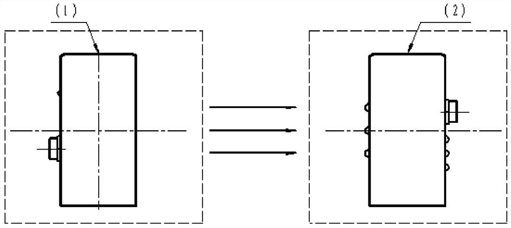
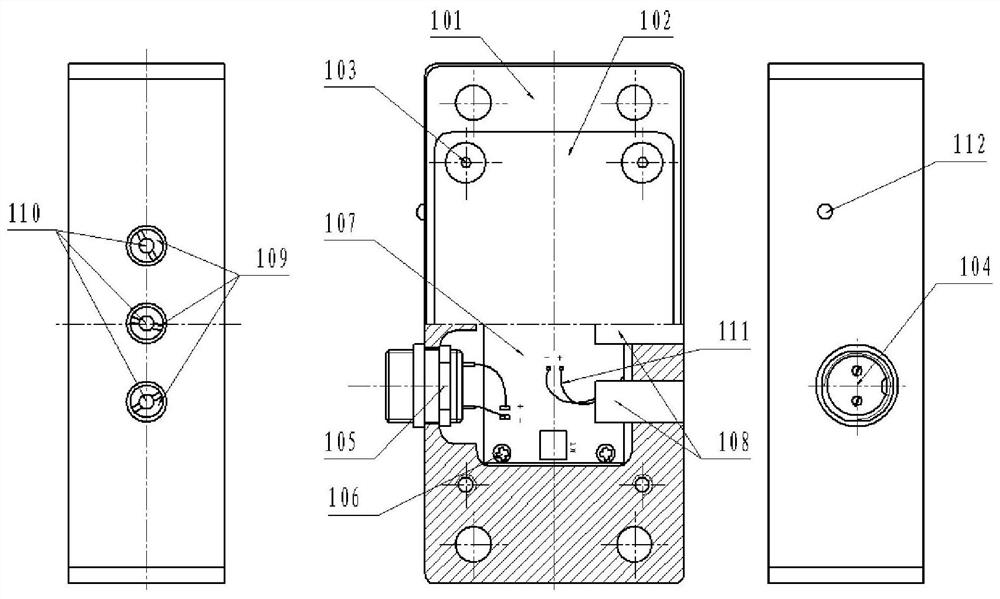
[0038] like figure 1 As shown, the high-speed response photoelectric test device includes a transmitter 1 and a receiver 2. When the transmitter 1 is powered on, the first emission state indicator 112 is on. When the first infrared emission tube 110 is aligned with the optical axis of the second receiving diode 209, the 2. The receiving status indicator light 210 is on, and when a flying object such as an explosive bolt head cuts off the optical axis, a level signal will be generated in turn. Therefore, the achievable functions of the present invention include:

[0039] First, the time detection function of the aerospace pyrotechnic separation devices such as explosive bolts from power-on to ignition is realized. Before detection, adjust the distance between the explosion bolt head and the first optical axis (bolt head acceleration section). When the explosion bolt is ...


PUM


Abstract

A high-speed response photoelectric test device includes a transmitter (1) and a receiver (2), and three pairs of transmitting tubes and receiving tubes that can form three optical paths are embedded at the symmetrical ends of the transmitter (1) and the receiver (2). tube, the three pairs of optical paths are perpendicular to the symmetrical ends and have equal distances. The high-speed response photoelectric test device includes a transmitting circuit and a receiving circuit, which can convert optical signals into electrical signals and output TTL levels. The response time of the invention is less than 5us, and the separation speed test of the aerospace pyrotechnic separation device mainly based on explosive bolts can be realized, the operation is convenient, and the reliability and accuracy requirements of the test can be guaranteed.

Description

technical field [0001] The invention relates to a high-speed response photoelectric testing device, which belongs to the application category of the photoelectric sensing technology field. Background technique [0002] The photoelectric test device is based on the principle of photoelectric conversion. The transmitter and the receiver are installed in pairs to align the optical paths. When an object passes through, the optical path cutoff signal is converted into a level signal. [0003] The aerospace pyrotechnic separation device, which is mainly based on explosive bolts, needs to perform a separation impulse test during the acceptance test to simulate the state of the bolt-like pyrotechnic product when it completes the specified function, and then determine its hazard to adjacent components. During the test, an optoelectronic test device is usually used to set the contact signal of the target point. By testing the flight time Δt of the bolt head and the distance L of the t...

Claims


Application Information

Patent Timeline
Patent Type & Authority Patents(China)
IPC IPC(8): G01D5/34
CPCG01D5/34
Inventor 周芳李春莹蒋春张勇孙平
Owner CHUANNAN MACHINERY PLANT CHINA ASTRONAUTIC SCI &TECH GROUP CORP
Why Eureka
Try Eureka