
Textile dust collecting device for textile machine

A technology of machine spinning dust and collecting device, which is applied in the direction of combination device, dispersed particle separation, chemical instrument and method, etc., can solve the problems of increasing work intensity, large space occupied by textile dust expansion, and short residence time of textile dust. , to achieve the effect of ensuring the use effect, reducing labor intensity and improving stability

Inactive Publication Date: 2018-03-23
WUHU RONGJI IND
View PDF4 Cites 7 Cited by
  • Summary
  • Abstract
  • Description
  • Claims
  • Application Information

AI Technical Summary

Problems solved by technology

As we all know, in the textile workshop, the textile machinery will produce a large amount of textile dust during the working process, which will affect the working environment of the workshop, and the staff work in this environment for a long time, which is not conducive to their health
In the process of collecting textile dust by the existing device, after the textile dust is absorbed by the device such as the induced draft fan, it will fall freely into the dust collection box. In this way, without power, the textile dust will adhere to the collector On the inner wall of the pipe, the efficiency of collecting textile dust becomes lower with the increase of time, and the expansion of textile dust leads to a larger space occupied by it. During the collection process, it needs to be processed frequently, which in turn increases the work. strength
[0003] Chinese patent application No. 201710575895.5 discloses a textile dust collection device for textile machines, including a box body, legs are provided on the left and right sides of the bottom of the box body, and the inner cavity of the box body is provided with a collection chamber. Connecting rods are arranged on the left and right sides of the top of the collecting chamber, and the top of the connecting rod is connected to the top of the inner cavity of the box body. A small water pump is arranged on the top of the box body, and a water pipe is connected to the outlet of the bottom of the small water pump. And the bottom of the water pipe runs through the top of the box body and the collection chamber respectively, and the bottom of the water pipe is provided with a nozzle, which passes through the collection chamber, small water pump, water pipe, nozzle, suction fan, suction pipe, filter screen, through pipe, and dust suction pipe. , the matching setting of the mounting seat and the inclined baffle can effectively absorb the waste dust generated when the textile machine is working, minimize the pollution of the workshop, reduce the physical harm to the operator, and provide a good environment for the operator. In the working environment, the water in this device cannot be recycled, and there is a defect of waste of resources
[0004] Chinese patent application No. 201710164363.2 discloses a textile dust collection device for textile machines, which includes a collection pipe and an impurity removal chamber. One end of the collection pipe is connected to a collection bucket, and the other end of the collection pipe is designed to be closed. An induced draft fan is installed near the other end of the collection pipe, a sprinkler device is fixed at the middle part above the inside of the collection pipe, a water distribution plate is fixed above the outside of the collection pipe, and a water distribution plate is fixed at the top of the outside of the collection pipe. Catheter, the bottom of the catheter is connected to a water collection tank, one side of the water collection tank is connected to a water guide, the impurity removal chamber is installed on the catheter, and the bottom of the impurity removal chamber is installed A push handle is installed on one side of the impurity removal chamber, and a push plate is fixed at one end of the push handle inside the impurity removal chamber. The textile dust in this device stays under the spray device for a short time, resulting in the textile dust being The effect of water adsorption is not good, and at the same time, personnel need to constantly push the push handle to clean the filter layer. If you forget to push the push handle or do not push the push handle for a long time, there is a hidden danger of water accumulation in the catheter

Method used


Image

  • Textile dust collecting device for textile machine
  • Textile dust collecting device for textile machine

Examples


Embodiment 1

[0017] In order to make the technical means, creative features, goals and effects achieved by the present invention easy to understand, the present invention will be further described below in conjunction with specific embodiments.

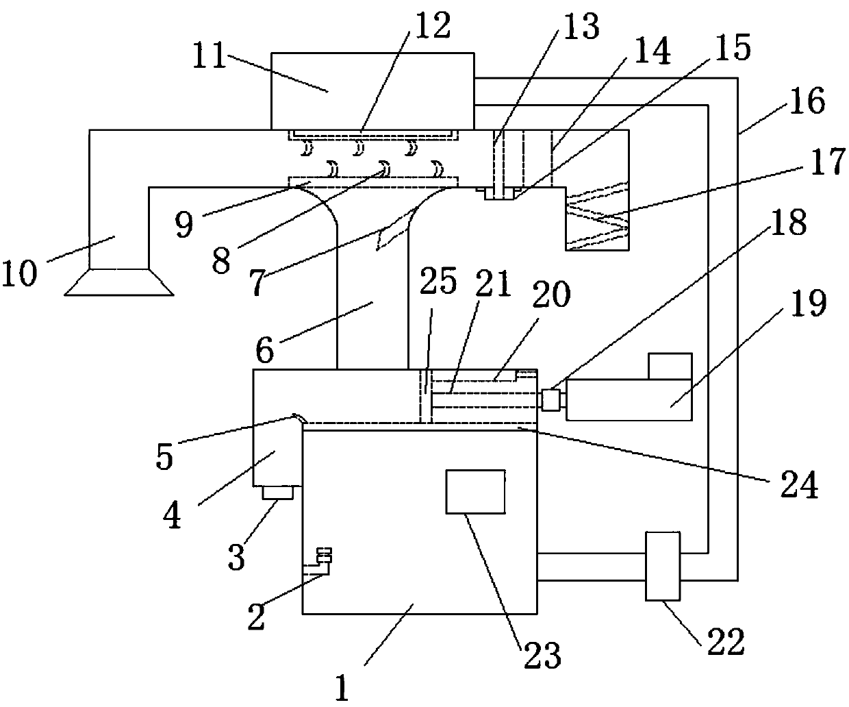
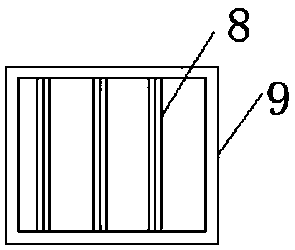
[0018] Such as Figure 1 to Figure 2 Shown, a kind of weaving machine weaving dust collecting device comprises collecting pipe 10, water tank one 11, water tank two 1, dust collecting pipe 6 and separating pipe 4, and one end of described dust collecting pipe 6 is connected with collecting pipe 10, The other end is connected with the separation pipe 4, the water tank one 11 is arranged above the collection pipe 10, the bottom of the water tank one 11 is provided with a shower head 12, and the water tank two 1 is arranged below the separation pipe 4, The water tank one 11 and the water tank two 1 are connected together by a water pipe 16, a water pump 22 is connected in series on the water pipe 16, an exhaust fan 14 is arranged in the collection pi...

Embodiment 2

[0021] Such as Figure 1 to Figure 2 Shown, a kind of weaving machine weaving dust collecting device, other steps in the present embodiment are identical with embodiment 1, difference is:

[0022] In this embodiment, the integrated pipe 6 is further provided with a sloping plate 7 . Effectively prevent the dust at the bottom of the dust collection pipe 6 from being sucked up by the wind.

[0023] In this embodiment, a liquid level switch 2 is also provided in the water tank 1, the position of the liquid level switch 2 corresponds to the position of the upper water pipe 16 of the water tank 1, and the liquid level switch 2 is connected to the controller 23 electrically connected together. When the water level in the water tank two 1 was lower than the liquid level switch 2, the liquid level switch 2 sent a signal to the controller 23, and the controller 23 controlled the water pump 22 to stop working, preventing the water pump 22 from air suction, causing the water pump 22 to...


PUM


Abstract

The invention discloses a textile dust collecting device for a textile machine, and relates to the technical field of textile equipment. The textile dust collecting device for the textile machine comprises a collecting tube, a first water tank, a second water tank, a dust collecting tube and a separating tube, wherein a spraying head is arranged at the bottom of the first water tank; the second water tank is arranged below the separating tube; the first water tank is connected with the second water tank through a water tube; the water tube is serially connected with a water pump; an exhaust fan and two buffering devices which are arranged at the upper end and the lower end of the inside of the collecting tube are arranged in the collecting tube; a filter layer is arranged in the separatingtube; and a cleaning device is further arranged at the position of the separating tube and comprises an electric cylinder, a straight rod, a push plate and a retractable rod. By the textile dust collecting device for the textile machine, the dust removal effect and the working effect of the filter layer are improved, and meanwhile, the working intensity of workers is relieved.

Description

technical field [0001] The invention relates to the technical field of textile equipment, in particular to a textile machine textile dust collection device. Background technique [0002] With the advancement of science and technology, my country's textile industry has developed rapidly in recent years, and with it comes the rapid development of prevention machinery. As we all know, in the textile workshop, the textile machinery will produce a large amount of textile dust during the working process, which will affect the working environment of the workshop, and the staff working in this environment for a long time is not conducive to their health. In the process of collecting textile dust by the existing device, after the textile dust is absorbed by the device such as the induced draft fan, it will fall freely into the dust collection box. In this way, without power, the textile dust will adhere to the collector On the inner wall of the pipe, the efficiency of collecting tex...

Claims


Application Information

Patent Timeline
IPC IPC(8): B01D47/06B01D50/00
CPCB01D47/06B01D50/60
Inventor 詹高
Owner WUHU RONGJI IND
Learn More