Pressure vessel

A technology for pressure vessels and hydraulic pumps, applied in the field of pressure vessels, can solve problems such as low sealing reliability, high cost, and complex sealing structure, and achieve the effects of high sealing reliability, low cost, and simple sealing structure

Inactive Publication Date: 2018-03-23
CHINA ENFI ENGINEERING CORPORATION
View PDF4 Cites 3 Cited by
  • Summary
  • Abstract
  • Description
  • Claims
  • Application Information

AI Technical Summary

Problems solved by technology

[0002] In the related art, for pressure vessels with stirring devices, such as stirring tanks and reaction kettles, the driving device for driving the stirring device to rotate is usually arranged outside the tank body of the pressure vessel, so that the output shaft of the driving device extends into the tank body. It is connected to the stirring device located in the tank, and a dynamic seal is used between the output shaft and the tank. This sealing method has the disadvantages of complex sealing structure, low sealing reliability and high cost.

Method used


Image

  • Pressure vessel

Examples


Embodiment Construction

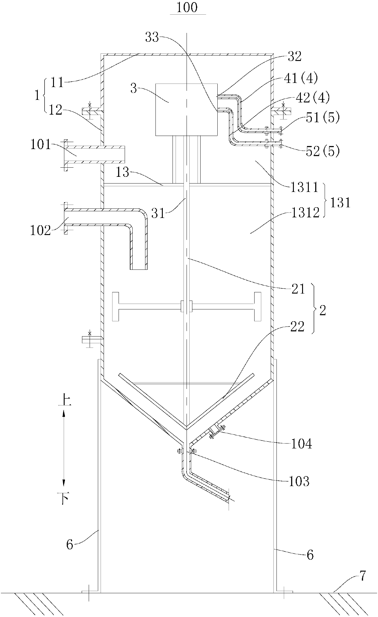
[0028] Embodiments of the present invention are described in detail below, examples of which are shown in the drawings, wherein the same or similar reference numerals designate the same or similar elements or elements having the same or similar functions throughout. The embodiments described below by referring to the figures are exemplary only for explaining the present invention and should not be construed as limiting the present invention.

[0029] In the description of the present invention, it should be understood that the orientations or positional relationships indicated by the terms "upper", "lower", "top", "bottom", "inner", "outer" etc. are based on the orientations shown in the drawings Or positional relationship is only for the convenience of describing the present invention and simplifying the description, but does not indicate or imply that the device or element referred to must have a specific orientation, be constructed and operated in a specific orientation, and...


PUM


Abstract

The invention discloses a pressure vessel. The pressure vessel comprises a tank, a stirring device and a hydraulic driving device, wherein an accommodating cavity is defined in the tank; the stirringdevice is arranged in the accommodating cavity; the hydraulic driving device comprises a hydraulic motor arranged in the tank and a hydraulic pump, a rotary output shaft of the hydraulic motor is connected with the stirring device to drive the stirring device to rotate, the hydraulic pump is arranged on the outer side of the tank, the hydraulic motor and the hydraulic pump are connected through aconnecting pipe assembly, and the connecting pipe assembly and the tank are in non-dynamic seal manner. According to the pressure vessel, sealing between the hydraulic driving device and the tank is simple, the sealing reliability is high, and the cost is low.

Description

technical field [0001] The invention relates to the technical field of pressure vessels, in particular to a pressure vessel. Background technique [0002] In the related art, for pressure vessels with stirring devices, such as stirring tanks and reaction kettles, the driving device for driving the stirring device to rotate is usually arranged outside the tank body of the pressure vessel, so that the output shaft of the driving device extends into the tank body. It is connected with the stirring device located in the tank, and a dynamic seal is used between the output shaft and the tank. This sealing method has the disadvantages of complex sealing structure, low sealing reliability and high cost. Contents of the invention [0003] The present invention aims to solve one of the technical problems in the related art at least to a certain extent. Therefore, the present invention proposes a pressure vessel, the sealing structure between the hydraulic drive device of the pressu...

Claims


Application Information

Patent Timeline
Patent Type & Authority Applications(China)
IPC IPC(8): B01J3/04B01F13/06
CPCB01J3/04B01F33/70
Inventor 施士虎贺茂坤谢盛青姚心吴世剑
Owner CHINA ENFI ENGINEERING CORPORATION
Why Eureka
Try Eureka