Side welding method of deformable metal foil structure with small initial inclined angle

A technology of initial angle and welding method, applied in welding equipment, welding equipment, metal processing equipment, etc., can solve the problems of difficult welding of deformable metal foil structures, achieve good sealing, increase post-weld strength, and structural sealing strong effect

Inactive Publication Date: 2018-11-02
ZHEJIANG UNIVERSITY OF SCIENCE AND TECHNOLOGY
View PDF5 Cites 3 Cited by
  • Summary
  • Abstract
  • Description
  • Claims
  • Application Information

AI Technical Summary

Problems solved by technology

[0005] The purpose of the present invention is to solve the problem of difficult welding of the side of the deformable metal foil structure with a small initial angle, and provide a side welding method for the deformable metal foil structure with a small initial angle

Method used


Image

  • Side welding method of deformable metal foil structure with small initial inclined angle
  • Side welding method of deformable metal foil structure with small initial inclined angle
  • Side welding method of deformable metal foil structure with small initial inclined angle

Examples


specific Embodiment approach 1

[0020] Specific implementation mode 1: This implementation mode is a side welding method of a deformable metal foil structure with a small initial angle, which is specifically completed according to the following steps:

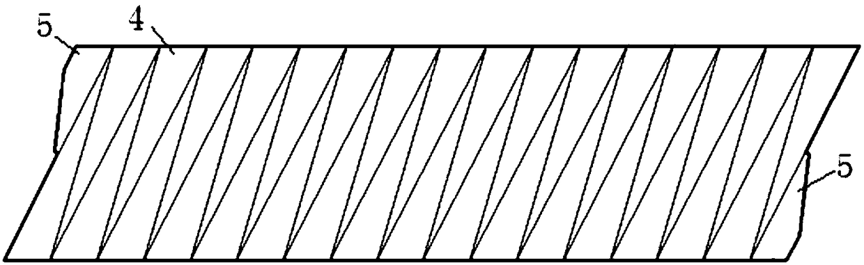
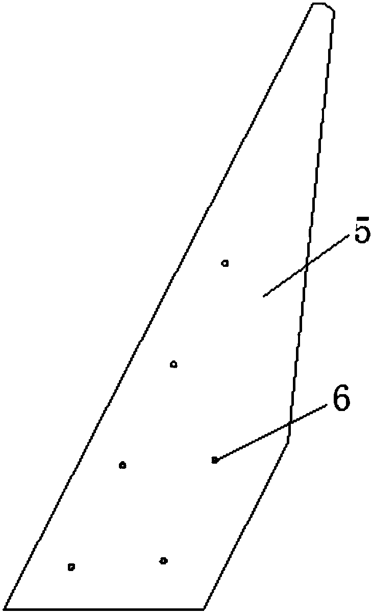
[0021] 1. Joints are arranged on both sides of the deformable metal foil structure foil sheet, the deformable metal foil structure foil sheet is parallelogram, and the deformable metal foil structure foil sheet is composed of multiple identical triangular blades Composition, the plane shape formed by two adjacent triangular blades is a parallelogram, the outermost two triangular blades of the deformable metal foil structure foil sheet are the blades to be welded, and the joint is set at the minimum of the longest hypotenuse of the blade to be welded Acute angle end, and the joint set on the blade to be welded is lap-welded with the blade to be welded on the other side. During lap welding, the joint will not interfere with other parts except the blade to be wel...

specific Embodiment approach 2

[0027] Embodiment 2: The difference between this embodiment and Embodiment 1 is that the deformable metal foil structure foil sheet in step 1 is composed of a plurality of identical triangular blades, and the longest hypotenuse of the triangular blades is The length is 207mm, the length of the shortest side is 40mm, and the angle of the smallest acute angle corresponding to the shortest side is 11°. Others are the same as the first embodiment.

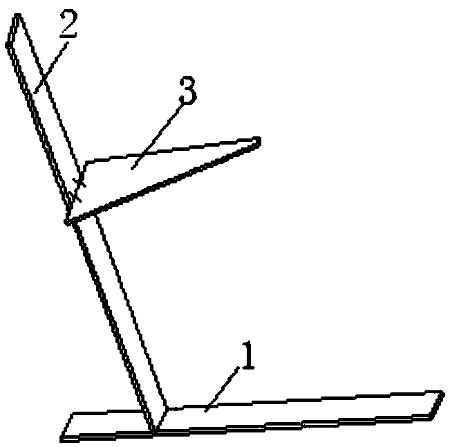
[0028] The included angle of the deformable metal foil structure with a small initial angle made of the deformable metal foil structure foil sheet provided in this embodiment is 35°.

specific Embodiment approach 3

[0029] Specific embodiment three: the difference between this embodiment and specific embodiment two is: the joint described in step one is hexagonal ABCDLK, the side AB of the hexagonal ABCDLK is on the extension line of the shortest side of the blade to be welded, and the side AK Coincident with the longest hypotenuse of the blade to be welded, the length of side AB is 30mm, the length of side BC is 28mm, the length of side CD is 65mm, the angle between side AB and side BC is 117°, the length of side BC and side CD The included angle is 159°, the side DL is a 45° chamfered side, and the length of the side DL is 2mm. Others are the same as in the second embodiment.


PUM

PropertyMeasurementUnit
angleaaaaaaaaaa

Abstract

The invention particularly relates to a side welding method of a deformable metal foil structure with a small initial inclined angle, and belongs to the field of special welding and connecting of deformable metal foil structures. The invention aims to solve the problem that the side of a deformable metal foil structure with a small initial inclined angle is difficult to weld. The side welding method comprises the following steps: first, the arrangement of a connector; second, the arrangement of six spot welding positions; third, compression molding to obtain a before-brazing deformable metal foil structure ; fourth, spot welding to obtain an after-spot welding structure; and fifth, the adoption of a heat treatment furnace to complete the side welding of the deformable metal foil structurewith the small initial inclined angle. The side welding method has the advantage of being capable of bearing 1.2 atm pressure difference. The side welding method is mainly used for side welding of thedeformable metal foil structure with the small initial inclined angle.

Description

technical field [0001] The invention belongs to the field of special welding and connection of deformable metal foil structures, and in particular relates to a side welding method of deformable metal foil structures with a small initial included angle. Background technique [0002] Deformable structures are widely used in aerospace because they can be folded and unfolded to change volume, and will not be destroyed during the folding process. Compared with the deformable structure made of polymer materials, the deformable structure made of metal has better overall rigidity and material strength, and at the same time has excellent performance in anti-ultraviolet radiation and setting performance after unfolding. Therefore, it has good application potential. At present, although there are reports on the application of deformable metal structures abroad, the relevant manufacturing technology has not been disclosed due to confidentiality reasons, while domestic research is in th...

Claims


Application Information

Patent Timeline
Patent Type & Authority Applications(China)
IPC IPC(8): B23K28/02B23K1/008
CPCB23K1/008B23K28/02
Inventor 聂大明曹丽丽祝邦文郑军马红萍管爱枝
Owner ZHEJIANG UNIVERSITY OF SCIENCE AND TECHNOLOGY
Why Eureka
Try Eureka