Eureka AIR delivers breakthrough ideas for toughest innovation challenges, trusted by R&D personnel around the world.

Cam for flat plate rolling type channelling machine

A kind of rolling groove machine, flat plate technology, applied in the field of rolling groove machine parts, can solve the problems of poor rotation, affecting the smooth progress of rolling groove, large power consumption and so on

Inactive Publication Date: 2018-03-23
潍坊江钢机械有限公司
View PDF0 Cites 0 Cited by
  • Summary
  • Abstract
  • Description
  • Claims
  • Application Information

AI Technical Summary

Problems solved by technology

The cam sleeve is in close contact with the surface of the camshaft. When the concave wheel drives the cam to rotate, the camshaft also rotates synchronously. Therefore, the transmission between the camshaft and the cam sleeve relies on frictional force, which consumes a lot of power, and it is easy to have a rotation difference with the concave wheel. And then affect the smooth progress of the rolling groove

Method used


Image

  • Cam for flat plate rolling type channelling machine
  • Cam for flat plate rolling type channelling machine
  • Cam for flat plate rolling type channelling machine

Examples


Embodiment Construction

[0016] Below in conjunction with accompanying drawing and embodiment, further elaborate the present invention. In the following detailed description, certain exemplary embodiments of the invention are described by way of illustration only. Needless to say, those skilled in the art would realize that the described embodiments can be modified in various different ways, all without departing from the spirit and scope of the present invention. Accordingly, the drawings and description are illustrative in nature and not intended to limit the scope of the claims.

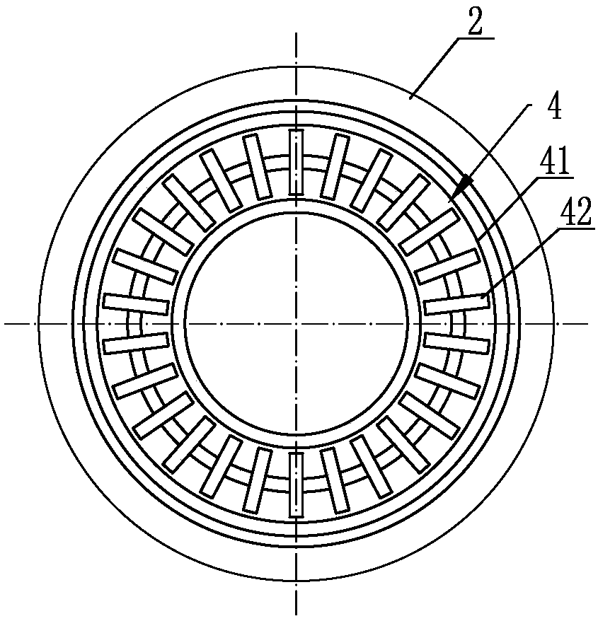
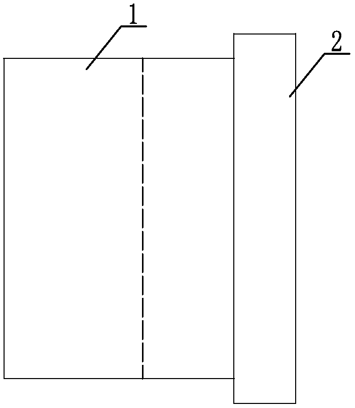
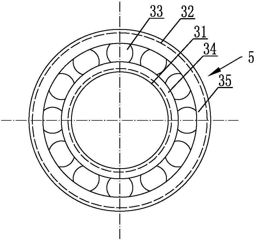
[0017] like figure 1 , figure 2 and image 3 As shown, the cam for flat rolling type grooving machine is installed on the grooving machine through the camshaft, including a cam sleeve 1, the outer periphery of the cam sleeve 1 is provided with a rolling groove pressing table 2, and the cam sleeve 1 and the rolling groove The pressing table 2 has an integrated structure, and the rolling groove pressing table 2 coopera...


PUM


Abstract

The invention discloses a cam for flat rolling type rolling grooving machine, which comprises a cam sleeve, the outer periphery of which is provided with a rolling groove pressing platform, and at least one roller bearing is set inside the cam sleeve, and the roller bearing Planar bearings are installed in the outer limit, and the cam sleeve, the rolling groove press table, the roller bearing and the plane bearing are coaxially arranged; the present invention is provided with a roller bearing in the cam sleeve, and the To realize the connection between the cam sleeve and the camshaft, plane bearings are provided on the contact surface between the two ends of the cam sleeve and the frame, and then when the pipe fitting and the cam are driven to rotate synchronously through the cooperation of the concave wheel and the friction force, due to the existence of the two bearings, no longer It is necessary to use friction to drive the synchronous rotation of the camshaft, so that the synchronous rotation of the cam sleeve and the rolling groove press table can be realized, and then the rolling ring groove is formed on the surface of the pipe fitting, the power consumption is small, the synchronization between the cam and the concave wheel is improved, and the rotation speed is avoided. The non-standard phenomenon of the rolling ring groove caused by the difference reduces the scrap rate.

Description

technical field [0001] The invention relates to the technical field of components for grooving machines, in particular to a cam for flat rolling grooving machines. Background technique [0002] The cam is one of the important components to complete the grooving process on the grooving machine. When rolling the groove, the cam and the concave wheel cooperate to clamp the pipe fitting. Driven by the power part, the concave wheel rotates. Through the friction between the concave wheel and the cam and the pipe fitting, the pipe fitting and the cam are driven to rotate synchronously to complete the pipe fitting. roll groove. The currently used cam has a one-piece structure, that is, it includes a cam sleeve for being sleeved on the camshaft, and a raised ring platform for rolling pipe fittings is formed on the outer surface of the cam sleeve. The cam sleeve is in close contact with the surface of the camshaft. When the concave wheel drives the cam to rotate, the camshaft also r...

Claims


Application Information

Patent Timeline
IPC IPC(8): B21D17/04
CPCB21D17/04
Inventor 程文智
Owner 潍坊江钢机械有限公司
Why Eureka
Eureka Blog
Learn More