Laser welding method and laser welding device

A laser welding, laser technology, applied in laser welding equipment, welding equipment, conductors and other directions, can solve the problem of low laser absorption rate

Active Publication Date: 2018-03-23
HONDA MOTOR CO LTD
View PDF10 Cites 2 Cited by
  • Summary
  • Abstract
  • Description
  • Claims
  • Application Information

AI Technical Summary

Problems solved by technology

In addition, it is known that copper used as such an electrical conductor has a low laser absorption rate, and a large-capacity laser emitter is used in order to shorten the time until the laser light is absorbed, and pretreatment such as surface oxidation is performed to increase the laser absorption rate.

Method used


Image

  • Laser welding method and laser welding device
  • Laser welding method and laser welding device
  • Laser welding method and laser welding device

Examples


Embodiment Construction

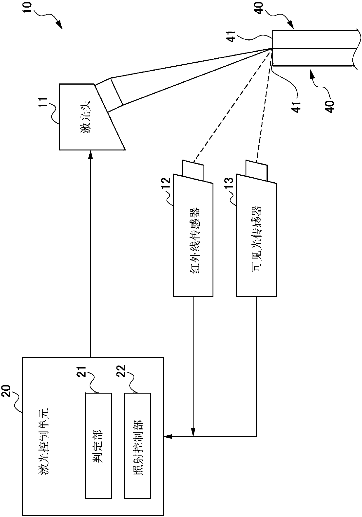
[0038] Preferred embodiments of the present invention will be described below with reference to the accompanying drawings. figure 1 It is a figure which shows typically the cell structure of the laser welding apparatus 1 which concerns on one Embodiment of this invention. The laser welding apparatus 1 of the present embodiment performs a laser welding method of joining at least two electrical conductors 40 by laser welding.

[0039] like figure 1 As shown, the laser welding apparatus 10 includes: a laser head 11 that irradiates a laser light (laser light) to an electrical conductor 40; an infrared sensor (photodetection unit) 12 that detects infrared light; a visible light sensor (photodetection unit) 13 that detects visible light; and The laser control unit 20 performs various controls of the laser welding apparatus 10 .

[0040] The laser head 11 is a laser irradiation unit that irradiates an infrared laser beam to a workpiece to be welded. The laser beam output from a ...


PUM


Abstract

The laser welding method includes: a step of applying, with a laser head(11), a laser to a joint part of electrical conductors(40) serving as metal members to be welded and detecting, with an infraredsensor(12), reflected light of the laser from the joint part or detecting, with a visible light sensor(13), light emitted from metal vapor; and a step of comparing the detection values of the infrared sensor(12) and the visible light sensor(13) and setting values respectively so as to determine whether or not energy absorption is started in the electrical conductors(40) and adjusting the controlof the application of the laser based on timing at which the energy absorption is determined to be started.

Description

technical field [0001] The present invention relates to a laser welding method and a laser welding apparatus for joining metal parts by laser welding. Background technique [0002] A technique for joining metal parts by laser welding has been conventionally known. For example, Patent Document 1 discloses such a technique. Patent Document 1 discloses a method of manufacturing a rotating electrical machine in which a rotating electrical machine is manufactured by inserting into each slot provided in a stator core, and joining by laser welding the tips of a plurality of electrical conductors protruding from the respective slots. motor. Furthermore, it is known that copper used as such an electrical conductor has a low laser absorptivity, a large-capacity laser emitter is used to shorten the time until laser light is absorbed, and a pretreatment such as surface oxidation is performed to increase the laser absorptivity. [0003] prior art literature [0004] Patent Literature...

Claims


Application Information

Patent Timeline
Patent Type & Authority Applications(China)
IPC IPC(8): B23K26/21B23K26/70
CPCB23K26/21B23K26/702B23K26/032B23K26/22B23K2101/38B23K26/705B23K26/32B23K31/125
Inventor 矢岛茂雄
Owner HONDA MOTOR CO LTD
Why Eureka
Try Eureka