Cutting equipment for electromobile tire recovering
A cutting equipment, electric vehicle technology, applied in recycling technology, plastic recycling, metal processing, etc., can solve problems such as uneven cutting and laborious placement
- Summary
- Abstract
- Description
- Claims
- Application Information
AI Technical Summary
Problems solved by technology
Method used
Image
Examples
Embodiment 1
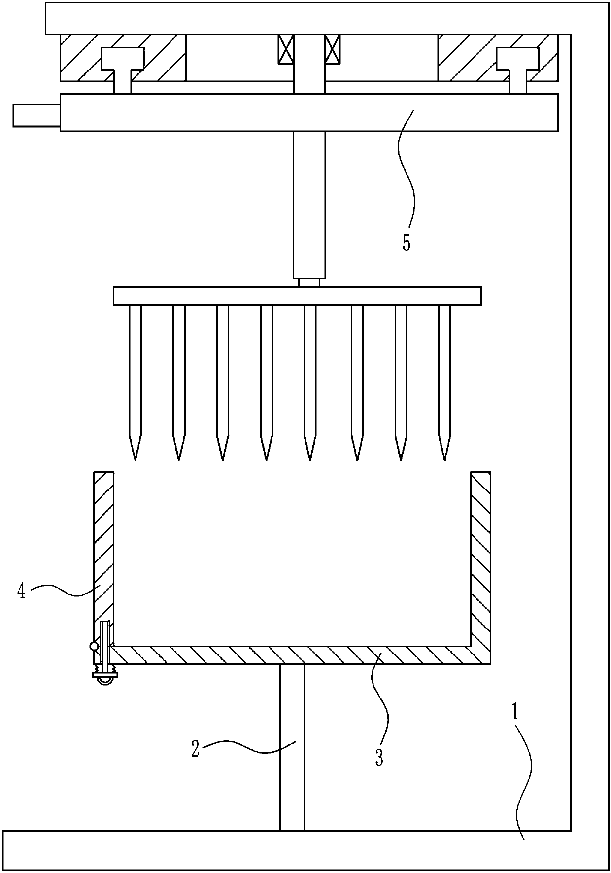
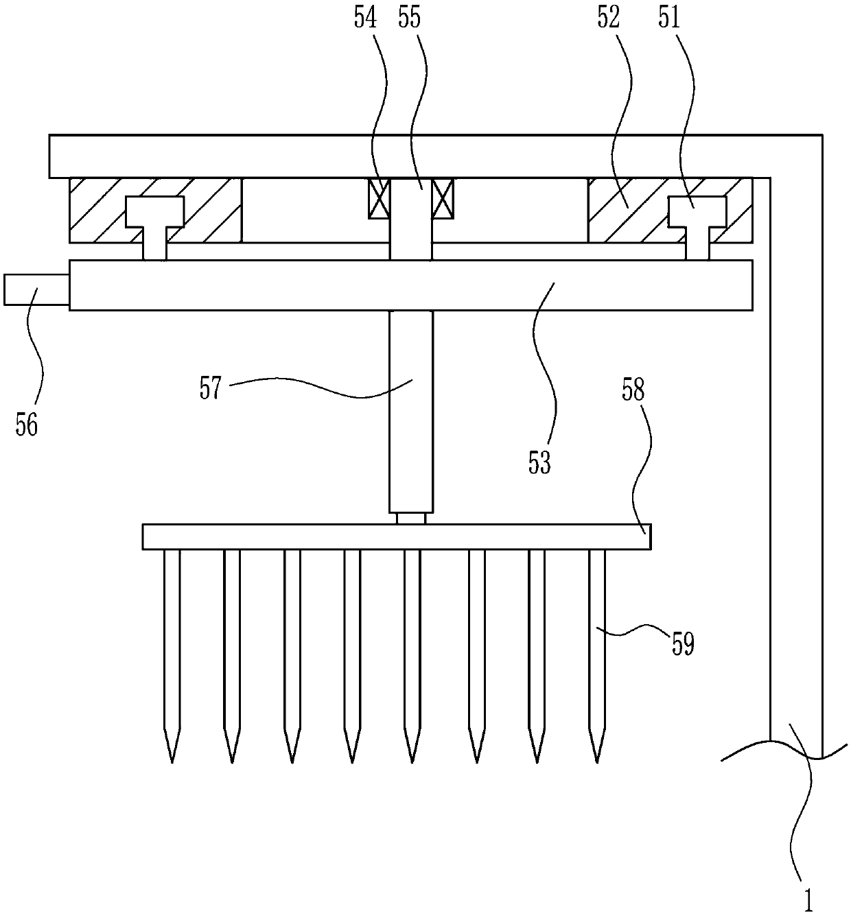
[0029] A cutting device for electric vehicle tire recycling, such as Figure 1-5 As shown, it includes a mounting frame 1, a pole 2, a frame body 3, a placement device 4 and a cutting device 5. The center of the bottom of the mounting frame 1 is provided with a pole 2, and the top of the pole 2 is connected to a frame body 3, and the frame body 3 The left part is provided with a placement device 4 , and the top of the installation frame 1 is provided with a cutting device 5 , which is above the frame body 3 .
Embodiment 2
[0031] A cutting device for electric vehicle tire recycling, such as Figure 1-5 As shown, it includes a mounting frame 1, a pole 2, a frame body 3, a placement device 4 and a cutting device 5. The center of the bottom of the mounting frame 1 is provided with a pole 2, and the top of the pole 2 is connected to a frame body 3, and the frame body 3 The left part is provided with a placement device 4 , and the top of the installation frame 1 is provided with a cutting device 5 , which is above the frame body 3 .
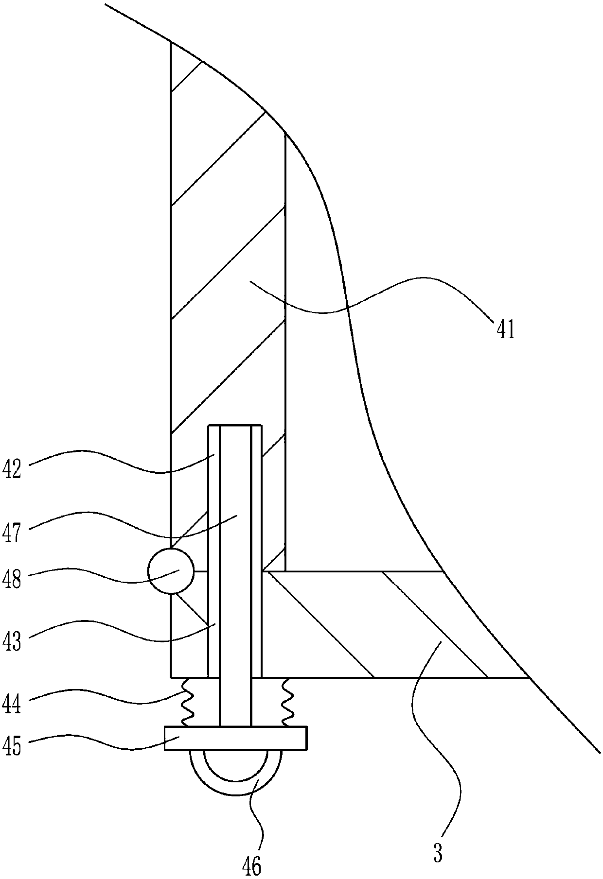
[0032]Placement device 4 comprises baffle plate 41, first spring 44, connecting plate 45, pull ring 46, inserting rod 47 and hinge 48, and frame body 3 inner bottom left side is connected with baffle plate 41 by hinge 48 rotatably, and baffle plate There is a groove 42 in the center of the bottom of 41, a through hole 43 is opened on the left side of the bottom of the frame body 3, and a first spring 44 is arranged symmetrically on the left and right sides of the bottom...
Embodiment 3
[0034] A cutting device for electric vehicle tire recycling, such as Figure 1-5 As shown, it includes a mounting frame 1, a pole 2, a frame body 3, a placement device 4 and a cutting device 5. The center of the bottom of the mounting frame 1 is provided with a pole 2, and the top of the pole 2 is connected to a frame body 3, and the frame body 3 The left part is provided with a placement device 4 , and the top of the installation frame 1 is provided with a cutting device 5 , which is above the frame body 3 .
[0035] Placement device 4 comprises baffle plate 41, first spring 44, connecting plate 45, pull ring 46, inserting rod 47 and hinge 48, and frame body 3 inner bottom left side is connected with baffle plate 41 by hinge 48 rotatably, and baffle plate There is a groove 42 in the center of the bottom of 41, a through hole 43 is opened on the left side of the bottom of the frame body 3, and a first spring 44 is arranged symmetrically on the left and right sides of the botto...
PUM
 Abstract
Description
Claims
Application Information
 - R&D
- Intellectual Property
- Life Sciences
- Materials
- Tech Scout
- Unparalleled Data Quality
- Higher Quality Content
- 60% Fewer Hallucinations
Browse by: Latest US Patents, China's latest patents, Technical Efficacy Thesaurus, Application Domain, Technology Topic, Popular Technical Reports.
© 2025 PatSnap. All rights reserved.Legal|Privacy policy|Modern Slavery Act Transparency Statement|Sitemap|About US| Contact US: help@patsnap.com


