Automatic grouting-type float-collar float-shoe device

A technology of self-grouting and floating hoops, which is applied to wellbore/well valve devices, drilling equipment, wellbore/well components, etc., which can solve problems such as stuck pipe, delayed casing running time, and unbalanced pressure, and achieve improved The effect of improving efficiency, improving drilling timeliness, and balancing internal and external pressure

Inactive Publication Date: 2018-03-23
潜江市联瑞石油机械有限公司
View PDF0 Cites 1 Cited by
  • Summary
  • Abstract
  • Description
  • Claims
  • Application Information

AI Technical Summary

Problems solved by technology

[0003] Due to the action of the one-way valve of the floating hoop and floating shoe in the lower structure of the casing, the pressure inside and outside the casing is unbalanced during the casing running process, so it is often necessary to stop and use the grouting pump to pour mud into the casing, resulting in the occurrence of problems during the grouting process. Downhole risks such as pipe sticking, obstruction, poor pump, etc., and delay in casing running time

Method used


Image

  • Automatic grouting-type float-collar float-shoe device

Examples


Embodiment Construction

[0010] Hereinafter, embodiments of the present invention will be described in detail with reference to the accompanying drawings.

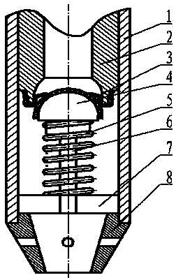
[0011] Such as figure 1 As shown, a self-grouting floating hoop floating shoe device is characterized by a shell 1, a body 2, a clip 3, a sealing hemisphere 4, a spring 5, a central rod 6, a fixing member 7, and a guide shoe 8. Embed four symmetrical clips 3 with a thickness of 8 mm, a width of 5 mm, and two wings of 10 mm on the sealing hemisphere of the one-way valve of the floating shoe, so that there is a gap of about 8 mm between the sealing hemisphere 4 of the one-way valve and the body 2.

[0012] The working principle of the automatic grouting floating hoop floating shoe of the present invention is that during the casing running process, there are four symmetrical ones with a thickness of 8 mm and a width of 5 mm on the sealing hemisphere of the one-way valve of the floating hoop floating shoe with 10 mm two wings. The clamp 3 makes a gap...


PUM


Abstract

A self-grouting floating hoop shoe device is characterized by the composition of a shell, a body, a clip, a sealing hemisphere, a spring, a central rod, a fixing piece, and a shoe guide. Embed four symmetrical clips with a thickness of 8 mm, a width of 5 mm, and two wings of 10 mm on the sealing hemisphere of the one-way valve of the floating hoop, so that there is a gap of about 8 mm between the sealing hemisphere of the one-way valve and the body. The clips are easy to make and install, and can realize automatic grouting during the casing running process, improve the casing running efficiency, reduce various risks in the casing running process, and improve the drilling efficiency.

Description

technical field [0001] The invention relates to a self-grouting type floating hoop floating shoe device. Background technique [0002] During the process of running the casing, due to the action of the one-way valve of the floating hoop and floating shoes of the lower structure of the casing, the operation process is often stopped, and a certain amount of mud is poured into the casing with a grouting device to balance the pressure inside and outside the casing and prevent pressure If the difference is too large, the casing and accessories will be damaged. However, during the process of stopping to grout, there are great downhole risks such as pipe sticking, obstruction, poor pump, etc., and the casing running time is delayed. There has been no good solution to this problem. Contents of the invention [0003] Due to the action of the one-way valve of the floating hoop and floating shoe in the lower structure of the casing, the pressure inside and outside the casing is unb...

Claims


Application Information

Patent Timeline
Patent Type & Authority Applications(China)
IPC IPC(8): E21B17/14E21B34/08
CPCE21B17/14E21B34/08
Inventor 周福新左志斌罗艳
Owner 潜江市联瑞石油机械有限公司
Why Eureka
Try Eureka