
Eureka
For R&D, Eureka makes reading and utilizing patents & technical documents easy.
Eureka AIR
Designed for self-driven R&D workflows. Generate viable solutions, solve complex R&D challenges, empower your innovation with AI.

Eureka Materials
Designed for material experts only. Revolutionize your material R&D, from search, analyze, to developing new materials.

TechResearch
Generate reliable direction feasibility study reports for your R&D in just a few steps.

TechSeek
Discover and master advanced knowledge NOW. Basics, ideas, possibilities, all at once.

TechMind
As an expert in R&D Theories, TechMind can generates customized viable solutions instantly.

TechRisk
Analyze your overall solution with one click, know your potential R&D risks in advance.

TechMonitor
Get weekly tech updates, stay abreast of the latest tech innovations and key insights.
Radial turbine of turbocharger and turbocharger
A technology of radial turbines and turbochargers, applied to gas turbine devices, machines/engines, mechanical equipment, etc.
- Summary
- Abstract
- Description
- Claims
- Application Information
AI Technical Summary
Problems solved by technology
Method used
Image

Examples
Embodiment Construction
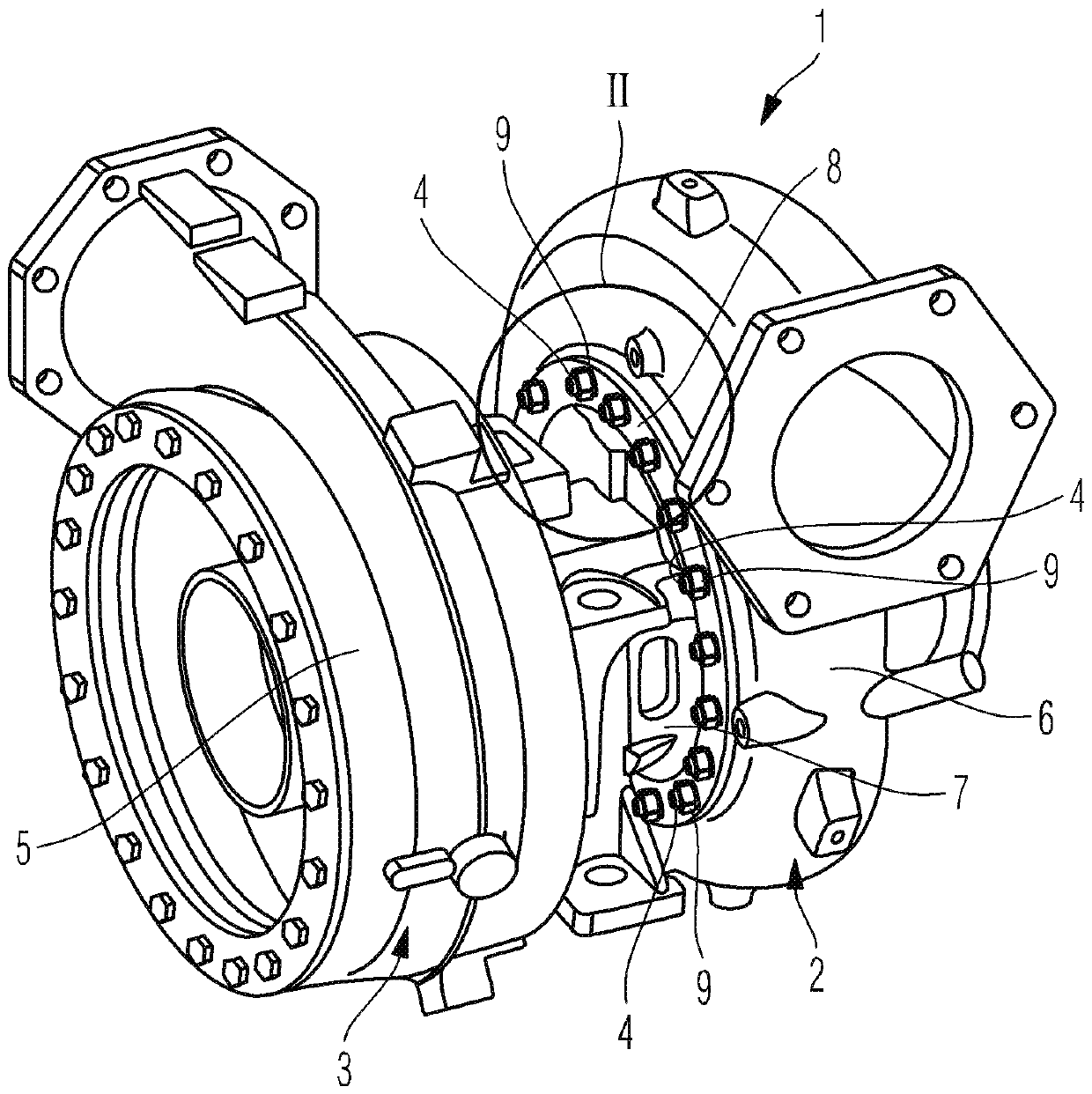
[0015] figure 1 A perspective view of a turbocharger 1 comprising a turbine 2 and a compressor 3 is shown. figure 1 The turbine 2 shown in is a radial turbine, and figure 1 The compressor 3 shown in is a radial compressor. In the turbine, the exhaust gas is expanded and the energy extracted in the process is used to compress the charge air in the compressor 3 .
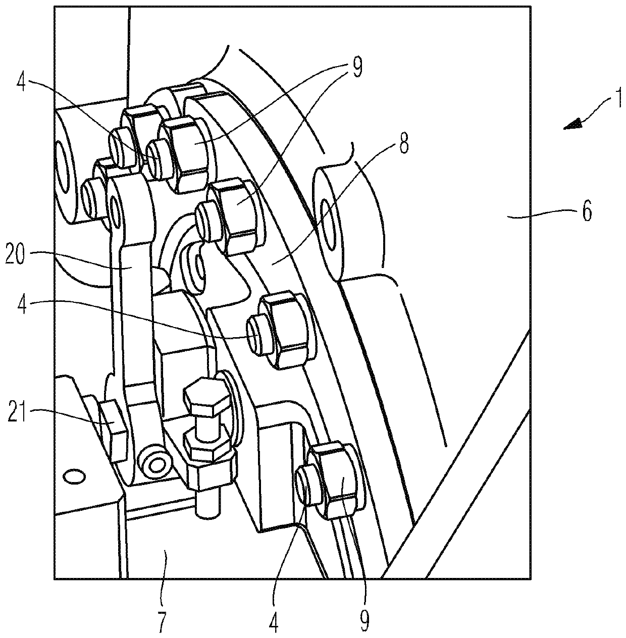
[0016] exist figure 1 , the turbine inflow housing 6 and the support housing 7 of the turbine 2 are shown, wherein the turbine inflow housing 6 and the support housing 7 are connected to each other via a fastening ring 8 which is also described as a clamping jaw . The fastening ring 8 is screwed to the turbine inflow casing 6 by means of several fastening screws 4 and fastening nuts 9 in such a way that, in the assembled state, the fastening ring 8 surrounds the bearing casing in sections 7 to engage the section 10 and thus mount the bearing housing 7 on the turbine inflow housing 6 . The compressor housing 5 of...
PUM
 Abstract
Description
Claims
Application Information
 - R&D Engineer
- R&D Manager
- IP Professional
- Industry Leading Data Capabilities
- Powerful AI technology
- Patent DNA Extraction
Browse by: Latest US Patents, China's latest patents, Technical Efficacy Thesaurus, Application Domain, Technology Topic, Popular Technical Reports.
© 2024 PatSnap. All rights reserved.Legal|Privacy policy|Modern Slavery Act Transparency Statement|Sitemap|About US| Contact US: help@patsnap.com