
Locking device of breaker operating device

A technology for operating devices and circuit breakers, applied in emergency protection devices, protective switch operation/release mechanisms, circuits, etc., can solve problems such as endangering equipment safety, and achieve the effect of ensuring safety

Active Publication Date: 2018-03-23
SHANGHAI LIANGXIN ELECTRICAL
View PDF4 Cites 8 Cited by
  • Summary
  • Abstract
  • Description
  • Claims
  • Application Information

AI Technical Summary

Problems solved by technology

[0003] Circuit breakers are divided according to installation methods: plug-in type, fixed type and drawer type. The use of plug-in type circuit breakers can effectively improve the safety of the electrical equipment industry. In order to meet the installation needs of various electrical equipment, the structure of the plug-in circuit breaker has also developed into various types. At present, in the layout of the existing traditional plug-in circuit breaker products in the installation position, generally press the operation button to break the circuit. When the circuit breaker is closed, the operation button of the circuit breaker springs back to reset after the operating force is removed, and the circuit breaker is disconnected when the button is pressed again; this traditional installation method does not matter whether the circuit breaker has been installed in the cabinet or not, the circuit breaker can be closed by pressing the operation button When the circuit breaker has been connected to the wire and the circuit breaker has been closed, when the circuit breaker is inserted into the cabinet, a small arc will be generated between the terminal of the circuit breaker and the bus bar, which may endanger the safety of nearby equipment

Method used


Image

  • Locking device of breaker operating device
  • Locking device of breaker operating device
  • Locking device of breaker operating device

Examples


Embodiment 1

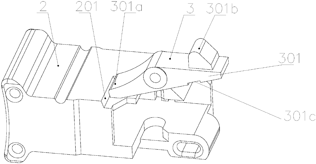
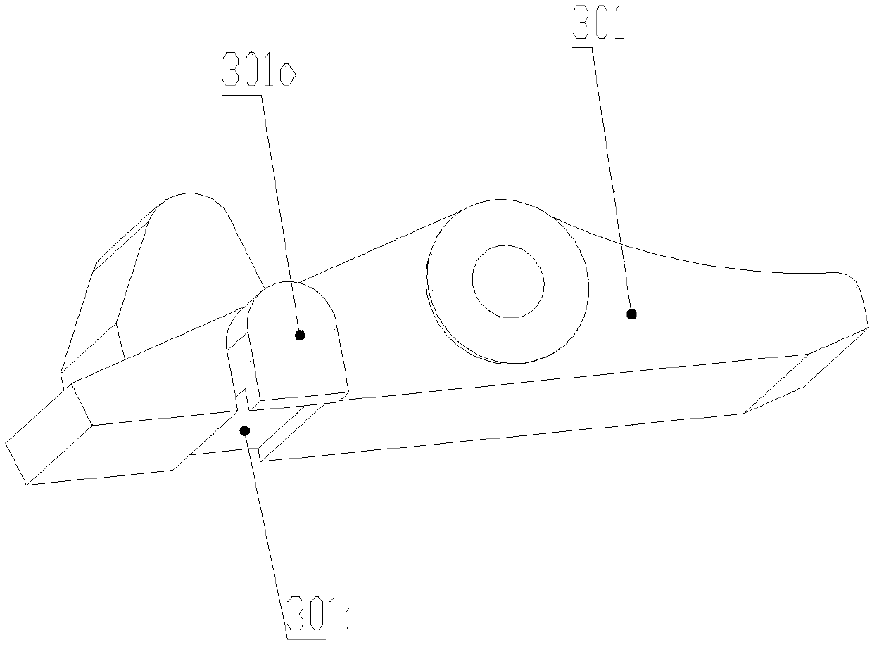
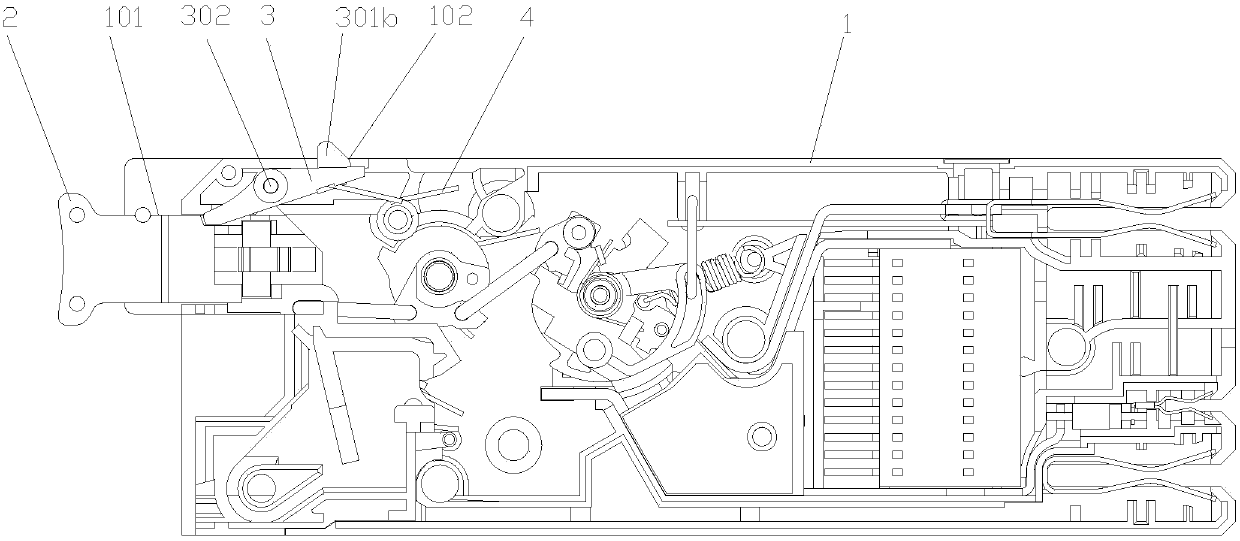
[0024] In a specific embodiment of the present invention, as attached figure 1 with 2 As shown, the locking mechanism 3 includes a lock button 301. The lock button 301 is mounted on the inner wall of the housing 1 through a shaft 302 and can rotate around the shaft 302. The left side is provided with a limiting boss 301a, the button 2 is provided with a limiting step 201 corresponding to the limiting boss 301a, and the lock button 301 is provided with a locking protrusion on the upper right end surface Table one 301b, the housing 1 is provided with a limiting slot 102 corresponding to the locking boss one 301b, as attached Figure 4 As shown, the torsion spring 4 is mounted on the housing 1, one end of the torsion spring 4 is placed on the housing 1, and the lock button 301 is provided with a groove 301c on the lower surface on the right side of the shaft 302, so The outer surface of the lock button 301 is provided with an undercut boss 301d corresponding to the groove 301c, and...

Embodiment 2

[0028] In another specific embodiment of the present invention, as attached Image 6 As shown, the locking mechanism 3 includes a second lock button 303. The second lock button 303 is mounted on the inner wall of the housing 1 through a second shaft 304 and can rotate around the second shaft 304. A limit rod 305 extends from the right side. The handle 5 is provided with a second limit step 501 corresponding to the limit rod 305. The handle 5 is mounted on the inner wall of the housing 1 through a shaft 3 6 to be able to go around the The shaft 3 6 rotates, the button 2 is connected with the handle 5 through the U-shaped connecting rod 7, the upper left end of the lock button 303 is provided with a locking boss 306, and the housing 1 is provided with a The second limit slot 103 corresponding to the second locking boss 306, the second torsion spring 8 is mounted on the second shaft 304, one end of the second torsion spring 8 is placed on the housing 1, and the other end is placed ...


PUM


Abstract

The invention relates to a locking device of a breaker operating device. The locking device comprises a casing (1) and a button (2) mounted in a button groove (101) of the casing (1) and is characterized in that the casing (1) is internally provided with a locking mechanism (3), and the locking mechanism (3) can lock or unlock the button (2). The locking device is advantaged in that the locking device is added to the internal portion of a breaker, only after pressing a lock button, an operation button is pressed to realize closing of the breaker, when the operation button is pulled out, the breaker is disconnected; when the lock button is not pressed, the operation button is locked by the lock button, the operation button can not be pressed, the breaker can not be closed, no arcs are generated between a wiring end of the breaker and a busbar, and safety of the equipment is guaranteed.

Description

Technical field [0001] The invention belongs to the technical field of circuit breakers, and specifically relates to a locking device of a circuit breaker operating device. Background technique [0002] Circuit breakers are divided into high-voltage circuit breakers and low-voltage circuit breakers according to their scope of use. Low-voltage plug-in circuit breaker, also known as automatic switch, is an electrical appliance that not only functions as a manual switch, but also can automatically protect against loss of voltage, undervoltage, overload and short circuit. It can be used to distribute electric energy, start asynchronous motors infrequently, protect power lines and motors, etc., and automatically cut off the circuit when they experience serious overload, short circuit, and undervoltage faults. Its function is equivalent to a fuse switch and The combination of overheating and underheating relays, and generally does not need to change parts after breaking the fault curr...

Claims


Application Information

Patent Timeline
Patent Type & Authority Applications(China)
IPC IPC(8): H01H71/10H01H9/24
CPCH01H9/24H01H71/1009H01H71/58H01H71/62H01H71/0214
Inventor 潘万军杨艳群
Owner SHANGHAI LIANGXIN ELECTRICAL
Learn More