Clearing device for insulating paint for auxiliary transformer iron core

A technology of auxiliary transformer and cleaning device, applied in the direction of removing smoke and dust, cleaning methods and utensils, chemical instruments and methods, etc., can solve the problem of recycling insulating paint before cleaning, and achieve the effect of convenient recycling

Active Publication Date: 2018-03-27
河北远大电子有限公司
View PDF5 Cites 1 Cited by
  • Summary
  • Abstract
  • Description
  • Claims
  • Application Information

AI Technical Summary

Problems solved by technology

[0004] Therefore urgently need to develop a kind of removal device for auxiliary transformer iron core that can fully remove the insulating varnish on the iron core, to overcome the shortcoming of recycling the insulating varnish on the iron core in the prior art

Method used


Image

  • Clearing device for insulating paint for auxiliary transformer iron core
  • Clearing device for insulating paint for auxiliary transformer iron core
  • Clearing device for insulating paint for auxiliary transformer iron core

Examples


Embodiment 1

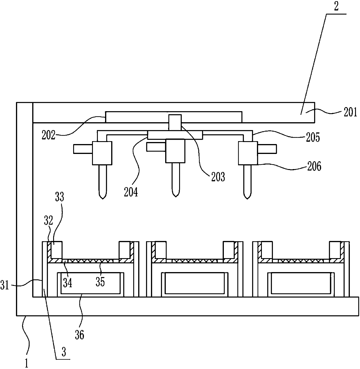
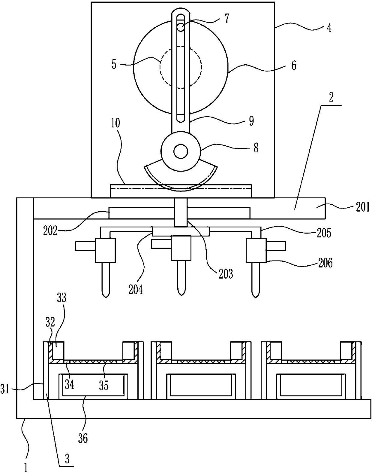
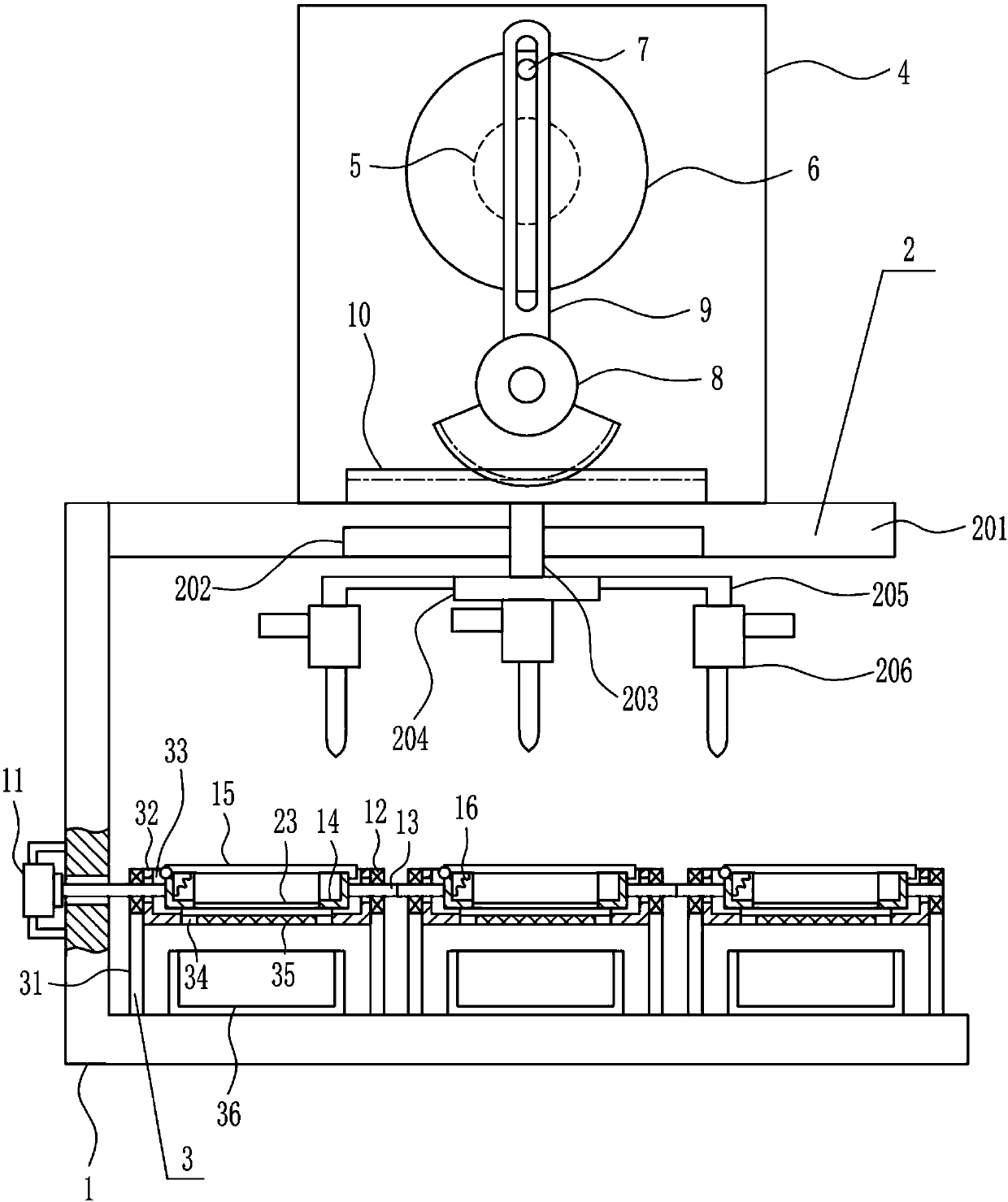
[0032] A device for removing insulating varnish for auxiliary transformer iron core, such as Figure 1-5 As shown, it includes a mounting frame 1, a fire-spraying mechanism 2 and a placement mechanism 3, the top of the mounting frame 1 is provided with a fire-spraying mechanism 2, and the bottom of the mounting frame 1 is provided with a placement mechanism 3.

Embodiment 2

[0034] A device for removing insulating varnish for auxiliary transformer iron core, such as Figure 1-5 As shown, it includes a mounting frame 1, a fire-spraying mechanism 2 and a placement mechanism 3, the top of the mounting frame 1 is provided with a fire-spraying mechanism 2, and the bottom of the mounting frame 1 is provided with a placement mechanism 3.

[0035] The flame spraying mechanism 2 includes the first mounting plate 201, the first slide rail 202, the first slide block 203, the connecting plate 204, the connecting rod 205 and the flame spray gun 206, the top of the mounting frame 1 is connected with the first mounting plate 201, the first The middle part of the mounting plate 201 is connected with a first slide rail 202, the first slide rail 202 is slidably connected with a first slide block 203, the first slide rail 202 cooperates with the first slide block 203, and the bottom end of the first slide block 203 is connected with The connecting plate 204 is symme...

Embodiment 3

[0037] A device for removing insulating varnish for auxiliary transformer iron core, such as Figure 1-5 As shown, it includes a mounting frame 1, a fire-spraying mechanism 2 and a placement mechanism 3, the top of the mounting frame 1 is provided with a fire-spraying mechanism 2, and the bottom of the mounting frame 1 is provided with a placement mechanism 3.

[0038] The flame spraying mechanism 2 includes the first mounting plate 201, the first slide rail 202, the first slide block 203, the connecting plate 204, the connecting rod 205 and the flame spray gun 206, the top of the mounting frame 1 is connected with the first mounting plate 201, the first The middle part of the mounting plate 201 is connected with a first slide rail 202, the first slide rail 202 is slidably connected with a first slide block 203, the first slide rail 202 cooperates with the first slide block 203, and the bottom end of the first slide block 203 is connected with The connecting plate 204 is symme...


PUM


Abstract

The invention relates to a clearing device, in particular to a clearing device for insulating paint for an auxiliary transformer iron core. According to the clearing device for the insulating paint for the auxiliary transformer iron core, the insulating paint on the iron core can be sufficiently cleared. The clearing device for the insulating paint for the auxiliary transformer iron core comprisesa mounting frame and the like, a fire spraying mechanism is arranged on the upper portion of the mounting frame, and a storing mechanism is arranged on the lower portion of the mounting frame. The fire spraying mechanism is arranged to sufficiently and completely clear the insulating paint on the iron core; the storing mechanism is arranged, and thus the discarded insulating paint on the iron core can be collected while the insulating paint on the discarded iron core can be cleared, so that recovery of the iron core and the insulating paint is facilitated; and a second sliding rail and a second sliding block are arranged so that taking and storing of a collecting frame can be facilitated, and the situation that the collecting frame is excessively heavy and thus cannot be smoothly moved out is prevented.

Description

technical field [0001] The invention relates to a cleaning device, in particular to a cleaning device for insulating varnish used in auxiliary transformer cores. Background technique [0002] A transformer is a device that uses the principle of electromagnetic induction to change the AC voltage. The main components are a primary coil, a secondary coil and an iron core (magnetic core). In electrical equipment and wireless circuits, it is often used for raising and lowering voltage, matching impedance, safety isolation, etc. The main functions are: voltage conversion, current conversion, impedance conversion, isolation, voltage stabilization (magnetic saturation transformer), etc. According to the purpose, it can be divided into: distribution transformers, power transformers, fully sealed transformers, combined transformers, dry-type transformers, oil-immersed transformers, single-phase transformers, electric furnace transformers, rectifier transformers, etc. [0003] The ir...

Claims


Application Information

Patent Timeline
Patent Type & Authority Applications(China)
IPC IPC(8): B08B7/00B08B13/00B08B15/04
Inventor 胡宇妠温旭胡玲玉
Owner 河北远大电子有限公司
Why Eureka
Try Eureka