A device for removing dust inside a window pulley slide

A technology of dust removal device and slide rail, which is applied in the direction of window cleaning, household utensils, cleaning equipment, etc. It can solve the problems of affecting work efficiency, long time consumption, and unclean cleaning inside the slide rail, etc., and achieves integrated high-efficiency, The effect of convenient operation of automation

Active Publication Date: 2022-07-22
江西金百成五金制品有限公司
View PDF11 Cites 0 Cited by
  • Summary
  • Abstract
  • Description
  • Claims
  • Application Information

AI Technical Summary

Problems solved by technology

[0004] In order to overcome the manual use of a vacuum cleaner to clean the dust in the slide rails, and then scrub and wipe, such operation steps are carried out one by one, which consumes a long time and affects work efficiency. It cannot be carried out at the same time, and manual cleaning The shortcoming that it is easy to clean the inside of the slide rail is not clean. The technical problem is: to provide a high-efficiency, dust-cleaning, brushing, and wiping integration at the same time, and does not require excessive manual operation. The internal dust removal device of the window pulley slide rail

Method used


Image

  • A device for removing dust inside a window pulley slide
  • A device for removing dust inside a window pulley slide
  • A device for removing dust inside a window pulley slide

Examples


Embodiment 1

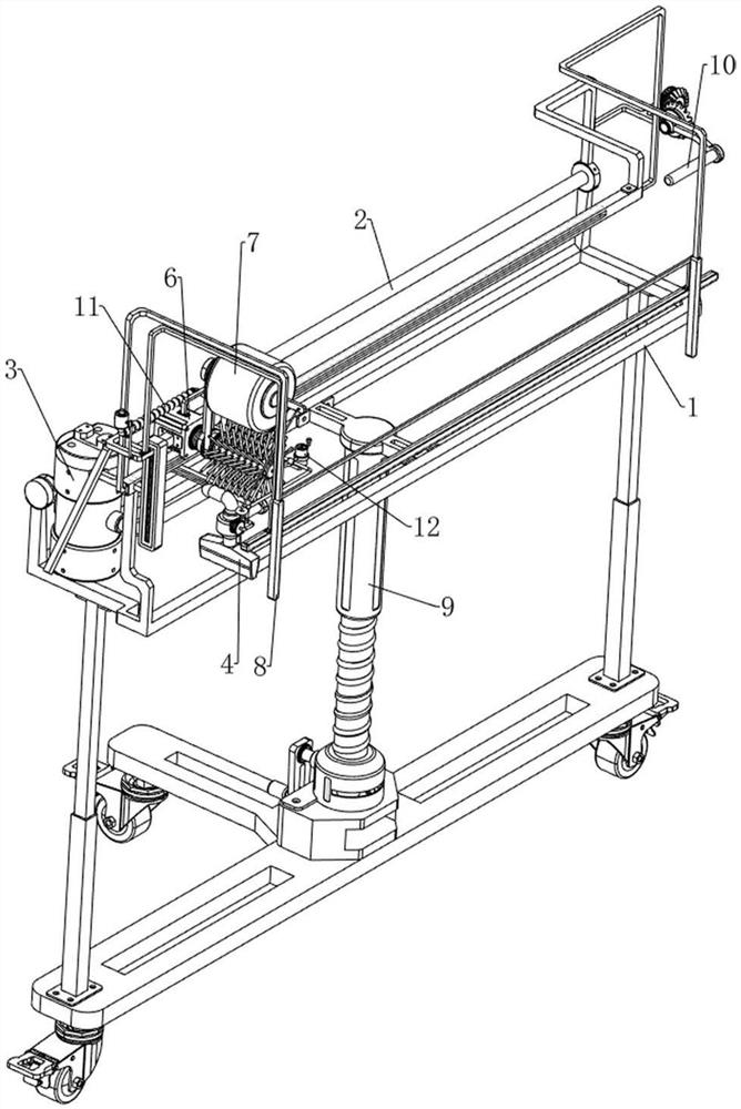
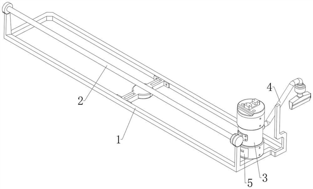
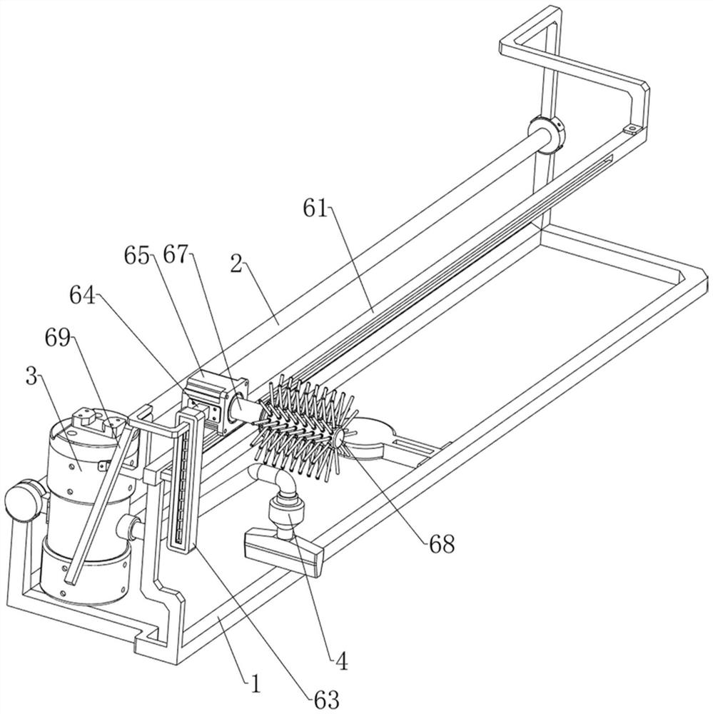
[0041] A device for removing dust inside a window pulley slide, such as Figure 1-8 As shown, it includes a first fixing frame 1, a first electric slide rail 2, a vacuum cleaner 3, a suction pipe 4, a material receiving frame 5, a brushing mechanism 6, a scrubbing mechanism 7 and a pulling mechanism 8. The upper part of the first fixing frame 1 The left side is provided with a first electric sliding rail 2, the front side of the first electric sliding rail 2 is slidably provided with a vacuum cleaner 3, the right side of the vacuum cleaner 3 is provided with a dust suction pipe 4, and the inner bottom of the vacuum cleaner 3 is slidably provided with a material receiving frame 5, The first fixing frame 1 is provided with a brushing mechanism 6 , the brushing mechanism 6 is provided with a scrubbing mechanism 7 , and the brushing mechanism 6 is provided with a pulling mechanism 8 , and the pulling mechanism 8 is located on the right side of the brushing mechanism 6 .

[0042] W...

Embodiment 2

[0049] On the basis of Example 1, as figure 1 , Figure 9 , Figure 10 , Figure 11 , Figure 12 , Figure 13 , Figure 14 , Figure 15 , Figure 16 and Figure 17As shown, it also includes an adjustment mechanism 9, and the adjustment mechanism 9 includes a second fixing frame 91, a first connecting rod 92, a connecting sleeve 93, a limit seat 94, a screw 95, a sleeve rod 96, a first bevel gear 97, a rocker The rod 98 and the moving wheel 99, the bottom of the first fixed frame 1 is symmetrical with the first connecting rod 92, the lower side of the two first connecting rods 92 is slidably provided with a second fixed frame 91, and the middle of the second fixed frame 91 is provided with The connecting sleeve 93 is provided with a limit seat 94 at the inner bottom of the connecting sleeve 93. The limit seat 94 is rotatably provided with a screw rod 95, the screw rod 95 is rotatably connected with the connecting sleeve 93, and the left side of the connecting sleeve 93 ...


PUM


Abstract

The invention relates to a dust removal device, in particular to a dust removal device inside a sliding rail of a window pulley. A device for removing dust inside a sliding rail of a window pulley, comprising: a first fixing frame; a first electric sliding rail, which is arranged on one side of the upper part of the first fixing frame; A vacuum cleaner for dust on the inner surface of the slide rail; a vacuum cleaner, a vacuum cleaner is provided with a vacuum cleaner on one side; a material collection frame, a sliding material collection frame for collecting dust is provided at the inner bottom of the vacuum cleaner. When working, the vacuum tube is located behind the cleaning brush, and the sponge brush is located in front of the cleaning brush. This can realize the method of cleaning first, then brushing, and finally wiping. The cleaning, brushing and wiping can be carried out at the same time, and the integration is more efficient. , and no manual operation is required, and the slide rail is cleaned more cleanly.

Description

technical field [0001] The invention relates to a dust removal device, in particular to a dust removal device inside a sliding rail of a window pulley. Background technique [0002] The sliding rail window is widely used to limit the window pulley, but the sliding rail space of this kind of window is narrow, and it is easy to accumulate dust and dirt. The traditional cleaning method is to use a vacuum cleaner to suck up the dust floating on the surface. , and then use a damp cloth in the slide rail to wipe off the stains that stick to the slide rail, or use a small brush for brushing. This traditional cleaning method is too inefficient, all manual and manual, and the internal space of the slide rail is narrow. , cleaning is troublesome. Implementing these cleaning steps one by one will affect the cleaning efficiency. One person cannot perform it well at the same time, and two people are required to cooperate to achieve rapid cleaning. Manual cleaning can also easily lead to ...

Claims


Application Information

Patent Timeline
Patent Type & Authority Patents(China)
IPC IPC(8): A47L1/02
CPCA47L1/02
Inventor 曾微罗仁波
Owner 江西金百成五金制品有限公司
Why Eureka
Try Eureka