Push type speed change mechanism

A speed change mechanism and push-type technology, which is applied in the direction of mechanical equipment, transmission devices, friction transmission devices, etc., can solve the problems of complex manufacturing, easy failure of the transmission mechanism, and inability to obtain high-torque transmission, so as to avoid the problem of high manufacturing accuracy Effect

Inactive Publication Date: 2018-03-27
MIHUMIS TECH CO LTD
View PDF8 Cites 1 Cited by
  • Summary
  • Abstract
  • Description
  • Claims
  • Application Information

AI Technical Summary

Problems solved by technology

[0005] The purpose of the present invention is to improve the defects in the prior art, such as complex manufacturing, easy failure of the transmission mechanism, and inability to obtain high torque transmission due to the use of gear-type transmission mechanisms. Through the implementation of the technical means of the present invention, the production process is simplified and avoids Transmission mechanism failure phenomenon, and can obtain high torque power transmission

Method used


Image

  • Push type speed change mechanism
  • Push type speed change mechanism
  • Push type speed change mechanism

Examples


Embodiment Construction

[0030] The technical means adopted by the present invention to achieve the intended invention purpose are further described below in conjunction with the drawings and preferred embodiments of the present invention.

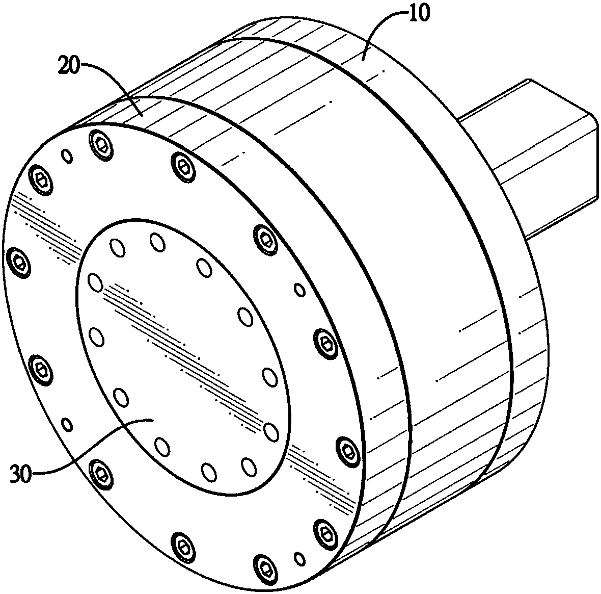
[0031] Please refer to figure 1 As shown, the first embodiment of the push-type transmission mechanism of the present invention has a power transmission unit 10 , a cover 20 and an output member 30 .

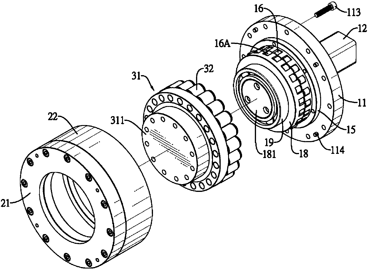
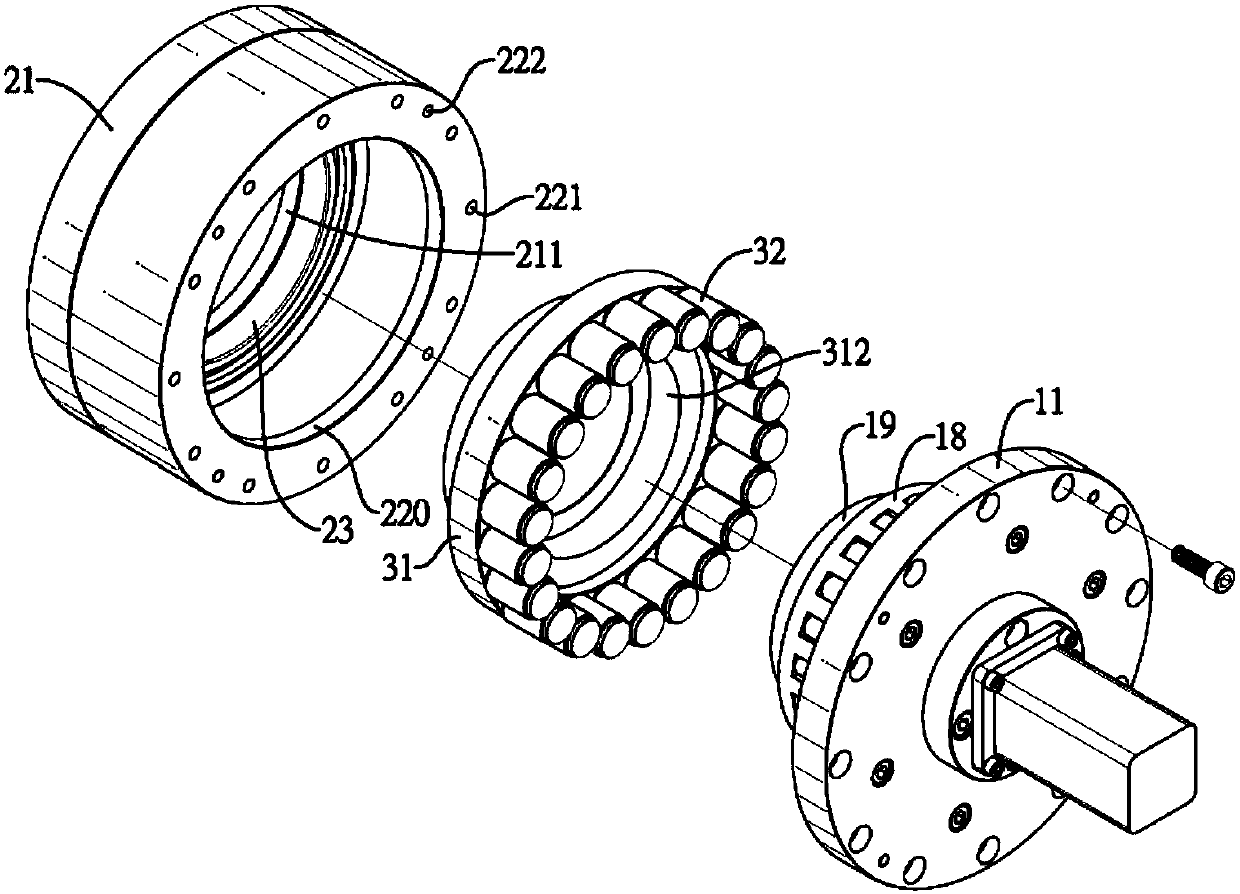
[0032] Please refer to figure 2 , 4 And shown in 6, this power transmission unit 10 has a base 11, a motor 12, a driving gear set 13, a base bearing 14, a first fixed disc 15, a plurality of transmission rolling elements 16, 16A, a drive Part 17 and a second fixed plate 18 and an output bearing 19.

[0033] The base 10 has an accommodating slot 110 , a setting platform 111 , at least one assembly column 112 , a plurality of coupling components 113 and a plurality of positioning components 114 .

[0034] The accommodating groove 110 is recessed and formed on one...


PUM


Abstract

The invention relates to a push type speed change mechanism which is provided with a base. The base is provided with a driving piece capable of rotating and is fixedly provided with a plurality of fixing discs, a plurality of cam parts are formed on the driving piece, the multiple fixing discs are each provided with a plurality of transmission rolling pieces capable of achieving radial displacement, the transmission rolling pieces can abut against the multiple cam parts to protrude out of the outer edge wall face, an annular continuous concave-convex structure is formed on the inner edge wallface of a transmission block, and the multiple transmission rolling pieces abut against the continuous concave-convex structure; the aim of speed change transmission is achieved through contact between the transmission rolling pieces and the continuous concave-convex structure of the transmission block, existing gear type speed reduction transmission is replaced, and the phenomenon of speed changemechanism damage caused by stress concentration is avoided; and meanwhile, a plurality of cam parts are adopted by the driving piece to drive the multiple transmission rolling pieces to achieve radial displacement, and the high-torsion transmission effect is achieved accordingly.

Description

technical field [0001] The invention relates to a speed change mechanism, in particular to a speed change mechanism which uses rollers to push against for contact transmission. Background technique [0002] The speed change mechanism is a deceleration transmission mechanism between the power source and the output end of the device (or equipment). The common application is to reduce the output speed of the prime mover, such as the engine and motor, and connect it to the driven output end , Such as: wheels, lathe chucks, reduce the original high speed to meet the speed requirements of actual use. [0003] The speed change mechanism commonly used in the prior art generally adopts gear-type speed change. Through the meshing and matching between gears of different sizes and different numbers of teeth, the power transmission and deceleration between the active source and the follower are achieved. However, in the gear-type speed change mechanism Among them, the manufacturing accu...

Claims


Application Information

Patent Timeline
Patent Type & Authority Applications(China)
IPC IPC(8): F16H13/08
Inventor 徐春腾
Owner MIHUMIS TECH CO LTD
Why Eureka
Try Eureka