[0075] Example 1
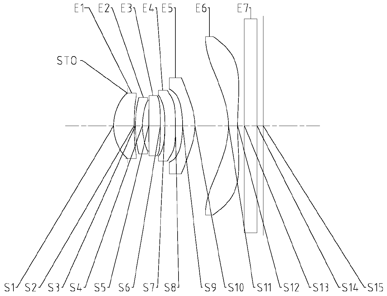
[0076] The following reference Figure 1 to Figure 2D The optical imaging lens according to Embodiment 1 of the present application is described. figure 1 A schematic structural diagram of an optical imaging lens according to Embodiment 1 of the present application is shown.
[0077] Such as figure 1 As shown, the optical imaging lens according to the exemplary embodiment of the present application includes in order from the object side to the image side along the optical axis: a stop STO, a first lens E1, a second lens E2, a third lens E3, and a fourth lens E4 , The fifth lens E5, the sixth lens E6, the filter E7 and the imaging surface S15.
[0078] The first lens E1 has a positive refractive power, the object side S1 is convex, and the image side S2 is concave. The second lens E2 has negative refractive power, the object side surface S3 is a convex surface, and the image side surface S4 is a concave surface. The third lens E3 has a positive refractive power, the object side surface S5 is a convex surface, and the image side surface S6 is a convex surface. The fourth lens E4 has negative refractive power, the object side surface S7 is concave, and the image side surface S8 is convex. The fifth lens E5 has a positive refractive power, the object side surface S9 is a concave surface, and the image side surface S10 is a convex surface. The sixth lens E6 has a negative refractive power, the object side surface S11 is a concave surface, and the image side surface S12 is a concave surface. The filter E7 has an object side surface S13 and an image side surface S14. The light from the object sequentially passes through each surface S1 to S14 and is finally imaged on the imaging surface S15.
[0079] Table 1 shows the surface type, radius of curvature, thickness, material, and conic coefficient of each lens of the optical imaging lens of Example 1, wherein the units of the radius of curvature and the thickness are millimeters (mm).
[0080]
[0081] Table 1
[0082] It can be seen from Table 1 that the object side surface and the image side surface of any one of the first lens E1 to the sixth lens E6 are aspherical surfaces. In this embodiment, the surface shape x of each aspheric lens can be defined by but not limited to the following aspheric formula:
[0083]
[0084] Among them, x is the distance vector height of the aspheric surface at a height h along the optical axis direction; c is the paraxial curvature of the aspheric surface, c=1/R (that is, the paraxial curvature c is the above table The reciprocal of the radius of curvature R in 1); k is the conic coefficient (given in Table 1); Ai is the correction coefficient of the i-th order of the aspheric surface. Table 2 below shows the high-order coefficient A that can be used for each aspheric mirror surface S1-S12 in Example 1. 4 , A 6 , A 8 , A 10 , A 12 , A 14 , A 16 , A 18 And A 20.
[0085] Face number A4 A6 A8 A10 A12 A14 A16 A18 A20 S1 -2.0654E-02 9.9813E-02 -4.6267E-01 1.3165E+00 -2.4168E+00 2.8586E+00 -2.0980E+00 8.6876E-01 -1.5472E-01 S2 -8.1455E-02 4.5637E-01 -1.3535E+00 3.2167E+00 -5.9473E+00 8.0665E+00 -7.3275E+00 3.9132E+00 -9.2602E-01 S3 -1.6639E-01 5.0861E-01 -1.1825E+00 2.2800E+00 -3.8242E+00 5.4921E+00 -5.8224E+00 3.7176E+00 -1.0493E+00 S4 -1.4579E-01 1.5925E-01 -1.4604E-01 -3.0112E-01 7.1166E-01 2.7449E-01 -2.4301E+00 2.8553E+00 -1.1258E+00 S5 9.3836E-03 -1.8393E-01 8.0243E-01 -2.0900E+00 2.9321E+00 -2.2114E+00 7.2507E-01 0.0000E+00 0.0000E+00 S6 -2.3849E-02 -2.8819E-02 1.0116E-01 -1.6003E-01 3.2623E-02 -2.0248E-03 5.6948E-03 0.0000E+00 0.0000E+00 S7 -1.3890E-01 -2.0358E-03 1.0722E-01 -1.4494E-01 1.8239E-01 -2.3906E-01 1.1554E-01 0.0000E+00 0.0000E+00 S8 -1.1690E-01 -4.1245E-02 -9.7302E-03 1.7842E-02 -1.9741E-03 -1.4455E-03 3.6581E-03 0.0000E+00 0.0000E+00 S9 8.7183E-02 -2.4667E-01 8.5391E-01 -2.2470E+00 3.4946E+00 -3.4576E+00 2.1617E+00 -7.7373E-01 1.1997E-01 S10 8.8217E-02 -1.6366E-01 4.7124E-01 -7.5286E-01 6.8146E-01 -3.6755E-01 1.1750E-01 -2.0587E-02 1.5236E-03 S11 -9.0140E-03 1.3641E-03 4.3495E-05 -3.4864E-06 -5.4808E-07 -1.9178E-08 3.8623E-09 0.0000E+00 0.0000E+00 S12 -2.1625E-02 2.0854E-03 -2.4296E-04 -8.8597E-06 9.6611E-07 1.1333E-07 -6.0665E-09 0.0000E+00 0.0000E+00
[0086] Table 2
[0087] Table 3 shows the effective focal length f1 to f6 of each lens in Example 1, the total effective focal length f of the optical imaging lens, the distance from the center of the object side S1 of the first lens E1 to the imaging surface S15 on the optical axis TTL and the imaging surface The effective pixel area on S15 is half the diagonal length of ImgH.
[0088]
[0089]
[0090] table 3
[0091] The optical imaging lens in Embodiment 1 satisfies:
[0092] T56/T23=5.20, where T56 is the separation distance between the fifth lens E5 and the sixth lens E6 on the optical axis, and T23 is the separation distance between the second lens E2 and the third lens E3 on the optical axis;
[0093] TTL/ImgH=1.36, where TTL is the distance from the center of the object side S1 of the first lens E1 to the imaging surface S15 on the optical axis, and ImgH is half of the diagonal length of the effective pixel area on the imaging surface S15;
[0094] f5/f6=-1.45, where f5 is the effective focal length of the fifth lens E5, and f6 is the effective focal length of the sixth lens E6;
[0095] f1/R1=2.13, where f1 is the effective focal length of the first lens E1, and R1 is the radius of curvature of the object side S1 of the first lens E1;
[0096] (R3+R4)/(R3-R4)=4.10, where R3 is the radius of curvature of the object side surface S3 of the second lens E2, and R4 is the radius of curvature of the image side surface S4 of the second lens E2;
[0097] CT1/CT6=2.25, where CT1 is the central thickness of the first lens E1 on the optical axis, and CT6 is the central thickness of the sixth lens E6 on the optical axis;
[0098] |f5/R10|=2.91, where f5 is the effective focal length of the fifth lens E5, and R10 is the radius of curvature of the image side surface S10 of the fifth lens E5;
[0099] |f/f5|+|f/f6|=2.14, where f is the total effective focal length of the optical imaging lens, f5 is the effective focal length of the fifth lens E5, and f6 is the effective focal length of the sixth lens E6;
[0100] R11/R12=-0.24, where R11 is the radius of curvature of the object side S11 of the sixth lens E6, and R12 is the radius of curvature of the image side S12 of the sixth lens E6;
[0101] TTL/ΣAT=2.81, where TTL is the distance from the center of the object side S1 of the first lens E1 to the imaging surface S15 on the optical axis, and ΣAT is the distance between any two adjacent lenses of the first lens E1 to the sixth lens E6. The sum of the separation distance on the axis;
[0102] |f6/CT6|=11.32, where f6 is the effective focal length of the sixth lens E6, and CT6 is the central thickness of the sixth lens E6 on the optical axis;
[0103] f/R12=0.45, where f is the total effective focal length of the optical imaging lens, and R12 is the radius of curvature of the image side surface S12 of the sixth lens E6;
[0104] T56/(T12+T23+T34)=2.71, where T56 is the distance between the fifth lens E5 and the sixth lens E6 on the optical axis, and T12 is the distance between the first lens E1 and the second lens E2 on the optical axis The distance, T23 is the separation distance between the second lens E2 and the third lens E3 on the optical axis, and T34 is the separation distance between the third lens E3 and the fourth lens E4 on the optical axis.
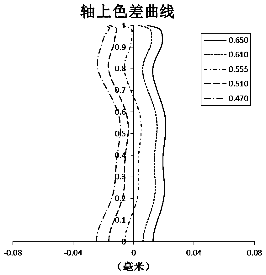
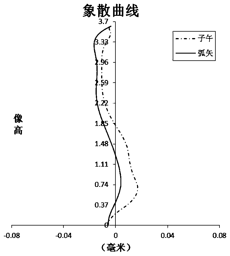
[0105] Figure 2A The axial chromatic aberration curve of the optical imaging lens of Example 1 is shown, which represents the deviation of the focusing point of light of different wavelengths after passing through the lens. Figure 2B The astigmatic curve of the optical imaging lens of Example 1 is shown, which represents meridional field curvature and sagittal field curvature. Figure 2C The distortion curve of the optical imaging lens of Example 1 is shown, which represents the magnitude of distortion under different viewing angles. Figure 2D The chromatic aberration curve of magnification of the optical imaging lens of Example 1 is shown, which represents the deviation of different image heights on the imaging surface after light passes through the lens. according to Figure 2A to Figure 2D It can be seen that the optical imaging lens given in Embodiment 1 can achieve good imaging quality.