
Circuit breaker handle connection mode

A connection method, circuit breaker technology, applied in circuits, protection switch operation/release mechanisms, electrical components, etc., can solve problems such as increased handle operating force, lever falling off, a lot of dust, etc., to achieve convenient production and debugging, and reliable limit. Effect

Active Publication Date: 2018-03-27
SHANGHAI LIANGXIN ELECTRICAL
View PDF6 Cites 2 Cited by
  • Summary
  • Abstract
  • Description
  • Claims
  • Application Information

AI Technical Summary

Problems solved by technology

However, in the existing installation methods of these handles and levers, when the handle is installed vertically, when the handle drives the lever to close and open the brake, the handle needs to be limited by the arc inside the middle cover of the circuit breaker. First, the operating force of the handle will be increased. , affecting the movement speed of the mechanism. Second, during the closing and opening process, it will cause friction between the handle and the middle cover and generate a lot of dust that will affect the moving parts of the mechanism. The third is that production and debugging are inconvenient. If there is no middle cover, the handle cannot be reliably connected with the lever. connection, it is easy to fall off from the lever, or even unable to close and open. In the process of production and debugging, other tools are needed to realize the closing and opening action of the product
When the handle is installed from the side, the limit of the handle is insufficient, and one side is fully open, so it is easy to slip out of the limit slot or cause friction with the side wall of the middle cover during use, which will also cause a lot of dust, etc. , affecting the performance of the product

Method used


Image

  • Circuit breaker handle connection mode
  • Circuit breaker handle connection mode
  • Circuit breaker handle connection mode

Examples


Embodiment Construction

[0022] The present invention will be further described below in conjunction with the accompanying drawings and embodiments.

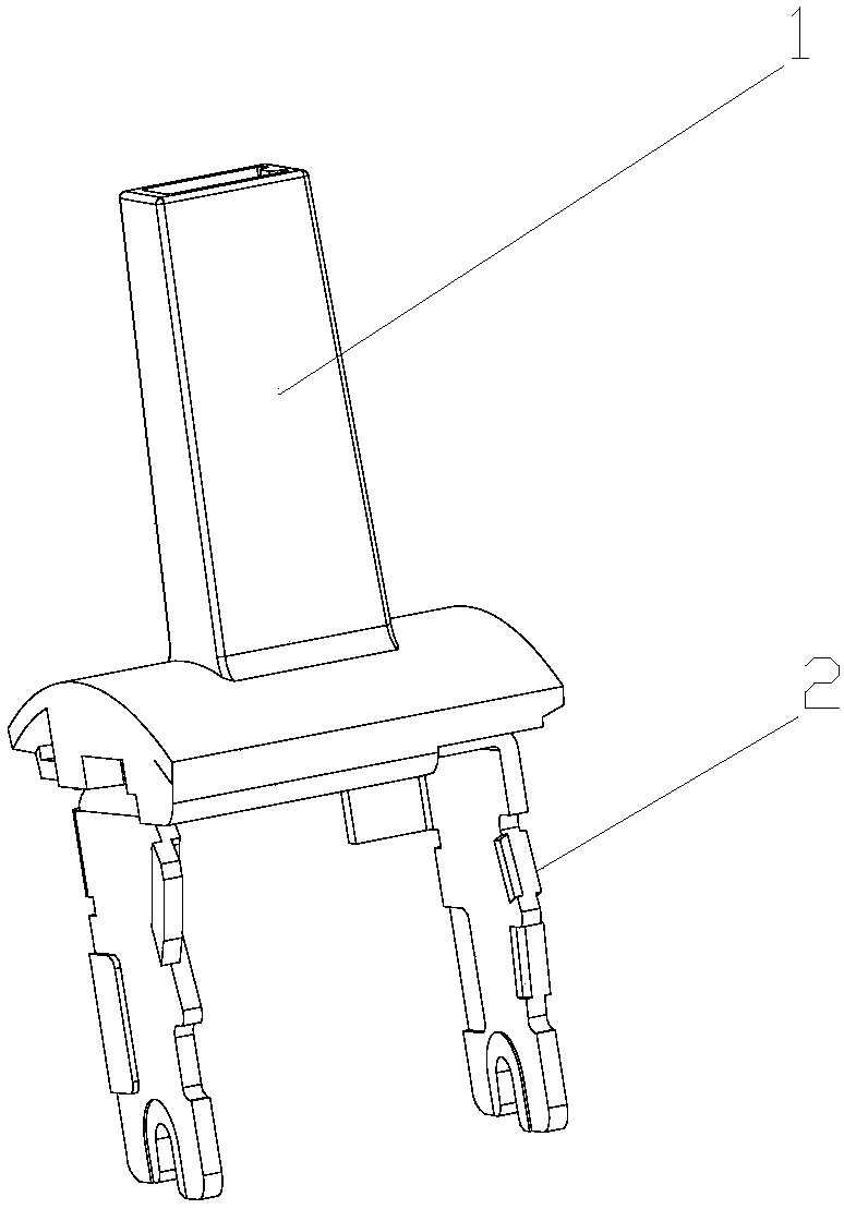
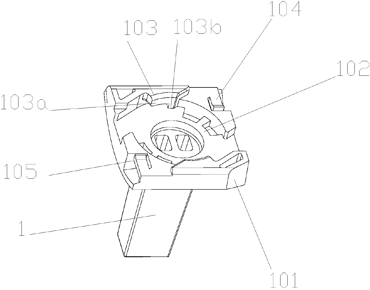
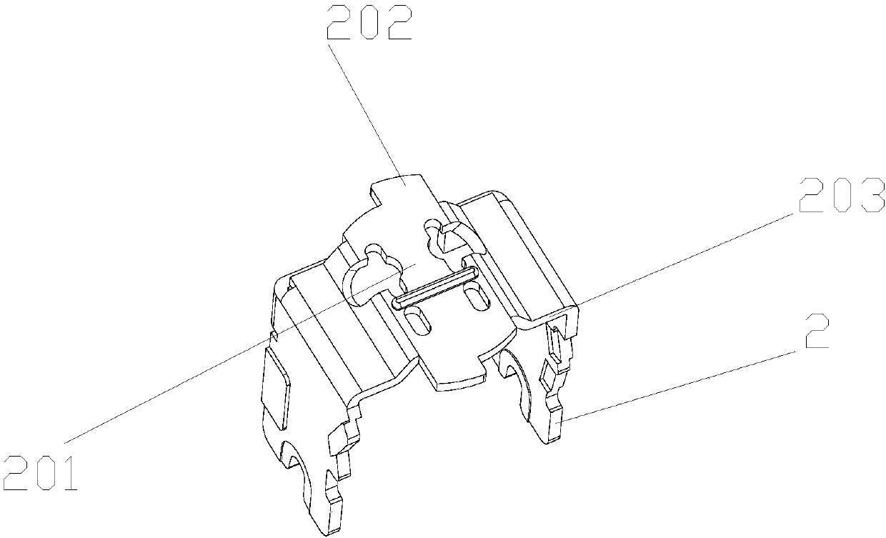
[0023] as attached figure 1 As shown, a circuit breaker handle connection method includes a handle 1 and a lever 2. In this embodiment, the lever 2 is U-shaped. The handle 1 and the lever 2 are installed together, wherein, the bottom of the handle portion 101 of the handle 1 is provided with a mounting groove 102, and the bottom 201 of the lever 2 is installed in the mounting groove 102 and can rotate. The bottom of the lever 2 protrudes from the positioning boss 202, and when the lever 2 is rotated to a fixed position in the installation groove 102, the positioning boss 202 is limited by the limit boss 103 so that it is installed in the installation groove 102. . Furthermore, a limit buckle 104 can also be added to further limit the degree of freedom so that it can be fixedly installed in the installation groove 102 . In this embodiment, there are t...


PUM


Abstract

The invention discloses a circuit breaker handle connection mode, which comprises a handle (1) and a lever (2). The handle (1) and the lever (2) are mounted together. The circuit breaker handle connection mode is characterized in that the bottom part of a handle disc part (101) of the handle (1) is provided with a mounting groove (102); the bottom part (201) of the lever (2) is mounted in the mounting groove (102) and can rotate; and when the lever (2) is rotated to a fixed position in the mounting groove (102), the degree of freedom is limited by limiting bosses (103) and the lever is thus mounted in the mounting groove (102). According to the circuit breaker handle connection mode, the lever and the handle adopt a rotating mounting mode, and while the cost of the handle and the cost of the lever are not increased, the handle can be reliably connected with the lever and limited.

Description

technical field [0001] The invention belongs to the technical field of circuit breakers, and in particular relates to a connection method of a circuit breaker handle. Background technique [0002] Circuit breakers are divided into high-voltage circuit breakers and low-voltage circuit breakers according to their scope of use. Low-voltage circuit breaker, also known as automatic switch, commonly known as "air switch", also refers to low-voltage circuit breaker. It is an electrical appliance that not only has the function of manual switch, but also can automatically protect against voltage loss, undervoltage, overload, and short circuit. It can be used to distribute electric energy, start asynchronous motors infrequently, protect power lines and motors, etc., and can automatically cut off the circuit when they have severe overload, short circuit and undervoltage faults. Its function is equivalent to a fuse switch and The combination of overheating and underheating relays, etc....

Claims


Application Information

Patent Timeline
Patent Type & Authority Applications(China)
IPC IPC(8): H01H71/52
CPCH01H71/52H01H71/521H01H71/10H01H71/0207H01H21/22
Inventor 李强蒋武山刘智操于贻鹏琚纪红
Owner SHANGHAI LIANGXIN ELECTRICAL
Learn More