
A device and method for single frequency network debugging

A single frequency network and equipment technology, applied in phase modulation carrier systems, color TV components, TV system components, etc., can solve the problems of difficulty in maintaining long-term stability of equipment operation, troublesome waveform observation, and few opportunities for debugging, etc. , to achieve the effect of facilitating the production and debugging of equipment, the method is simple and fast, and easy to popularize

Active Publication Date: 2017-02-22
CHINA BROADCAST CORP
View PDF3 Cites 0 Cited by
  • Summary
  • Abstract
  • Description
  • Claims
  • Application Information

AI Technical Summary

Problems solved by technology

The resulting problem is that the oscilloscope used needs a bandwidth of 500--800 MHz. This oscilloscope is expensive, dozens of times the price of an ordinary oscilloscope with a bandwidth below 20 MHz; Observation is also more troublesome. Although some single-frequency transmission network equipment can be set to the debugging state, causing the transmission waveform to be partially depressed for easy observation, but the equipment debugging is troublesome, and it does not get rid of the expensive oscilloscope
The cost of equipment debugging is high, and there are few opportunities for debugging, which makes it difficult to maintain long-term stability of equipment operation

Method used


Image

  • A device and method for single frequency network debugging
  • A device and method for single frequency network debugging
  • A device and method for single frequency network debugging

Examples


Embodiment 1

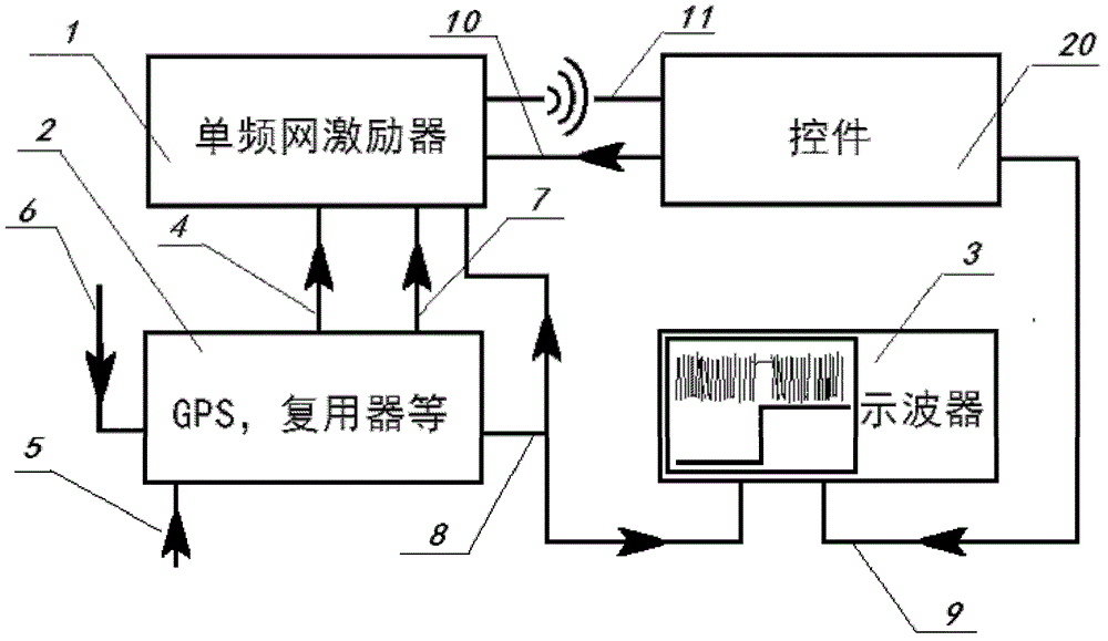
[0020] Embodiment 1. Controls and methods for single frequency network debugging, the schematic diagram is as follows figure 1 shown. The antenna receiving signal 6 and the broadcast data 5 of the global positioning timing system GPS enter the GPS receiver and the network multiplexer 2, and the GPS receiver and the network multiplexer 2 output the time and date and the reference frequency signal 7, the reference second pulse signal 8 and the multiplexer Use the data signal 4 to the single frequency network exciter 1; the single frequency network exciter 1 sends out the digital TV radio frequency signal 11; the control unit 20 receives the digital TV radio frequency signal 11 and controls the frequency sent by the single frequency network exciter 1 through the communication line 10 As well as the transmitter identification signal, the output low-frequency demodulation signal 9 is sent to the oscilloscope 3; the demodulation signal 9 is compared with the reference second pulse s...

Embodiment 2

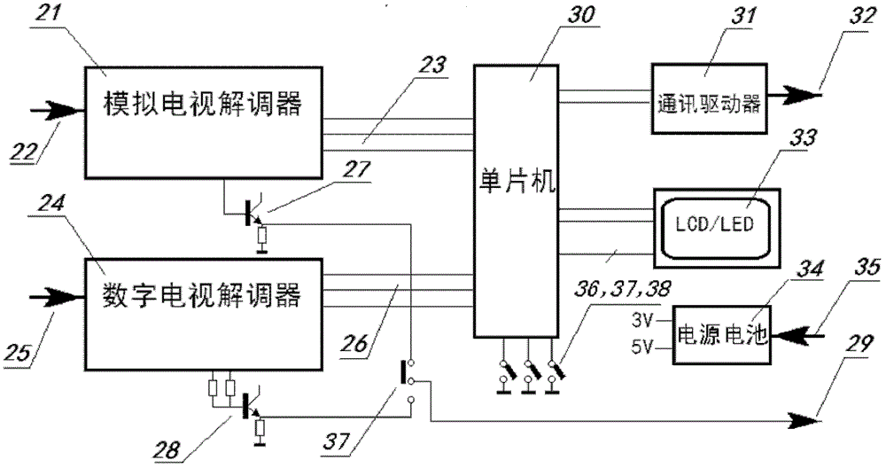
[0021] Embodiment 2, the control that is used for SFN debugging, its schematic diagram is as follows figure 2 shown. Controls include single-chip microcomputer and demodulator connected with single-chip microcomputer, interface, key display, power supply and so on.

[0022] There are two receiving paths for the digital TV radio frequency signal sent by the single frequency network exciter: the analog TV demodulator 21 receives the digital TV radio frequency signal from the interface 22, and the video signal demodulation output reaches the jumper socket 37 through the isolator 27; The demodulator 24 receives the digital TV radio frequency signal from the interface 25, and the IQ signal demodulation output reaches the jumper socket 37 through the isolator 28, and one path is selected through the jumper socket 37 and sent to the oscilloscope through the output socket 29.

[0023] The single-chip microcomputer 30 controls the analog TV demodulator 21 through the serial data bus ...

Embodiment 3

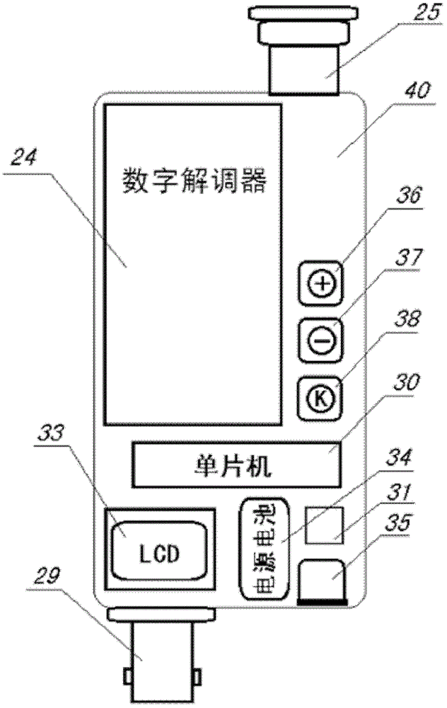
[0026] Embodiment 3, the control that is used for single frequency network debugging, it adopts the control structural diagram of digital TV demodulator as image 3 shown. Use the control of digital TV demodulator 24 to be installed in the casing 40, radio frequency input plug 25 and demodulation output socket 29 are respectively arranged at two ends, wherein have single-chip microcomputer 30 and drive circuit 31, three buttons 36,37,38 adjust respectively Channel and control SFN exciter, LCD digital tube 33 displays channel number, the power consumption of the whole machine is small, can work with rechargeable battery, mini USB socket 35 is used for charging, power supply and communication with SFN exciter.


PUM


Abstract

The invention provides a piece of equipment for debugging a single frequency network and a method for debugging a single frequency network. Controls comprise a single chip microcomputer, a demodulator, a port, a power supply, button displays and the like; and the controls are structured by using an equivalence processing method of time domain synchronization or frequency domain transformation so as to control a specified data bit of a transmitted waveform. With the controls and method for debugging the single frequency network provided by the invention, a phase of the specified data bit in a debugged low-frequency signal is observed and compared to judge the synchronization performance of a high-frequency carrier and adjust the carrier; a common oscilloscope with a low price is used for observing and adjusting the phase so as to complete the debugging of the single frequency network, therefore expensive oscilloscopes above 500 MHz do not need to be used; the production debugging, online networking of the equipment are convenient; the method is simple and fast; and the structured controls are portable, low in costs and easy to popularize.

Description

technical field [0001] The invention belongs to the field of mobile multimedia broadcasting, and in particular relates to a device and method for single frequency network debugging. Background technique [0002] At present, in the equipment debugging of the digital single-frequency transmission network, the phase comparison between the reference second pulse and the transmission signal is usually carried out on the oscilloscope, so as to judge whether the phase lock is stable and adjust the phase of the equipment. The resulting problem is that the oscilloscope used needs a bandwidth of 500--800 MHz. This oscilloscope is expensive, dozens of times the price of an ordinary oscilloscope with a bandwidth below 20 MHz; Observation is also troublesome. Although some single-frequency transmission network equipment can be set to the debugging state, causing the transmission waveform to be partially depressed for easy observation, the equipment debugging is cumbersome and does not ge...

Claims


Application Information

Patent Timeline
Patent Type & Authority Patents(China)
IPC IPC(8): H04N5/38H04N17/00H04L27/20
Inventor 孙朝晖余英刘波隋志国王欣刚唐涛周红君李旭朱剑锋刘宝民
Owner CHINA BROADCAST CORP
Learn More