Device for simulating a force on an actuation element of a vehicle, in particular a pedal force simulator

A technology for manipulating elements and simulators, applied in the direction of brakes, etc., can solve the problems of expensive and laborious manufacturing, and achieve the effects of simplifying manufacturing, reducing costs, and preventing jamming

Active Publication Date: 2018-03-27
SCHAEFFLER TECH AG & CO KG
View PDF6 Cites 4 Cited by
  • Summary
  • Abstract
  • Description
  • Claims
  • Application Information

AI Technical Summary

Problems solved by technology

This is laborious and expensive to manufacture

Method used


Image

  • Device for simulating a force on an actuation element of a vehicle, in particular a pedal force simulator
  • Device for simulating a force on an actuation element of a vehicle, in particular a pedal force simulator
  • Device for simulating a force on an actuation element of a vehicle, in particular a pedal force simulator

Examples


Embodiment Construction

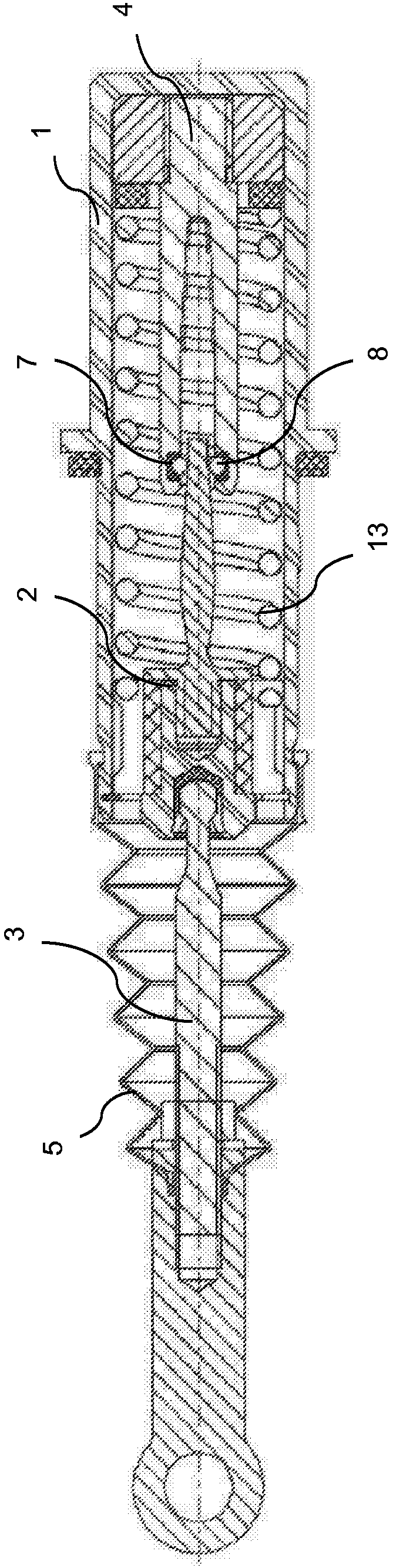
[0025] figure 1 A device for force simulation is shown, as is known from the as yet unpublished prior art. The device has a housing 1 inside which a piston 2 can move axially. Piston 2 is connected via piston rod 2 to an operating element (eg clutch pedal). A dust protection device 5 in the form of a bellows is arranged on the outside of the piston rod in the radial direction. The dust protection device is fixed on the piston rod 3 and on the housing 1 and prevents dirt particles from entering the interior of the cylinder. The piston rod 3 has a piston rod head, not shown in detail, which is supported in the joint socket of the piston 2 . The piston 2 consists of a piston element and a connecting rod member, which are connected to each other. The linkage component has a changing cross section and is pushed axially into the spring element 4 when the actuating element is actuated.

[0026] The spring element 4 is fork-shaped and has two spring arms. as from figure 1 It ca...


PUM


Abstract

The invention relates to a device for simulating a force on an actuation element of a vehicle, in particular a pedal force simulator, comprising a housing (10), a piston (20) which can be moved axially in the housing (10), said piston (20) being connected to the actuation element via a piston rod (30), and a spring element (40) which is arranged at least partly within the housing (10), in particular completely within the housing. According to the invention, the piston (20) has a changing cross-section and engages into the spring element (40) upon being actuated by the actuation element. The spring element (40) is equipped with rolling bodies (70, 80) which are operatively connected to the piston (20), and the spring element (40) consists at least of a first and a second spring part (50, 60) which are connected together.

Description

technical field [0001] The invention relates to a device for force simulation on an actuating element of a vehicle, in particular a pedal force simulator, having a housing and an axially displaceable piston in the housing and a spring element, wherein the piston Via the piston rod being connected to the actuating element, the spring element is arranged at least partially, in particular completely, inside the housing. Background technique [0002] Actuating systems are known in which no direct mechanical or hydraulic connection is provided between clutch pedal and clutch. In such actuation systems, sensors in the pedal or in the pedal force simulator detect the actuation of the pedal and control the disengagement or engagement of the clutch accordingly. The force required to actuate the clutch pedal for the disengagement action no longer exists due to the lack of counterforce from the clutch. Therefore, in order that the clutch actuation does not appear unfamiliar to the dr...

Claims


Application Information

Patent Timeline
Patent Type & Authority Applications(China)
IPC IPC(8): B60T8/32
CPCB60T8/3255B60T8/4086
Inventor M·巴斯勒S·洪泽尔曼
Owner SCHAEFFLER TECH AG & CO KG
Why Eureka
Try Eureka