
scroll compressor

A scroll compressor and compression mechanism technology, applied in the field of scroll compressors, can solve problems such as the reduction of compressor operating efficiency, and achieve the effects of reducing the amount of lubricating oil, restraining the supply amount, and restraining the reduction of operating efficiency

Active Publication Date: 2019-04-12
MITSUBISHI HEAVY IND THERMAL SYST
View PDF1 Cites 0 Cited by
  • Summary
  • Abstract
  • Description
  • Claims
  • Application Information

AI Technical Summary

Problems solved by technology

Therefore, the lubricating oil mixed in the fluid seals the minute gap between the laps of the fixed scroll and the orbiting scroll, thereby suppressing a decrease in the operating efficiency of the compressor.

Method used


Image

  • scroll compressor
  • scroll compressor
  • scroll compressor

Examples


Embodiment Construction

[0024] Hereinafter, embodiments according to the present invention will be described in detail with reference to the drawings. In addition, this invention is not limited to this embodiment. In addition, the constituent elements in the following embodiments include those that can be easily replaced by those skilled in the art, or those that are substantially the same.

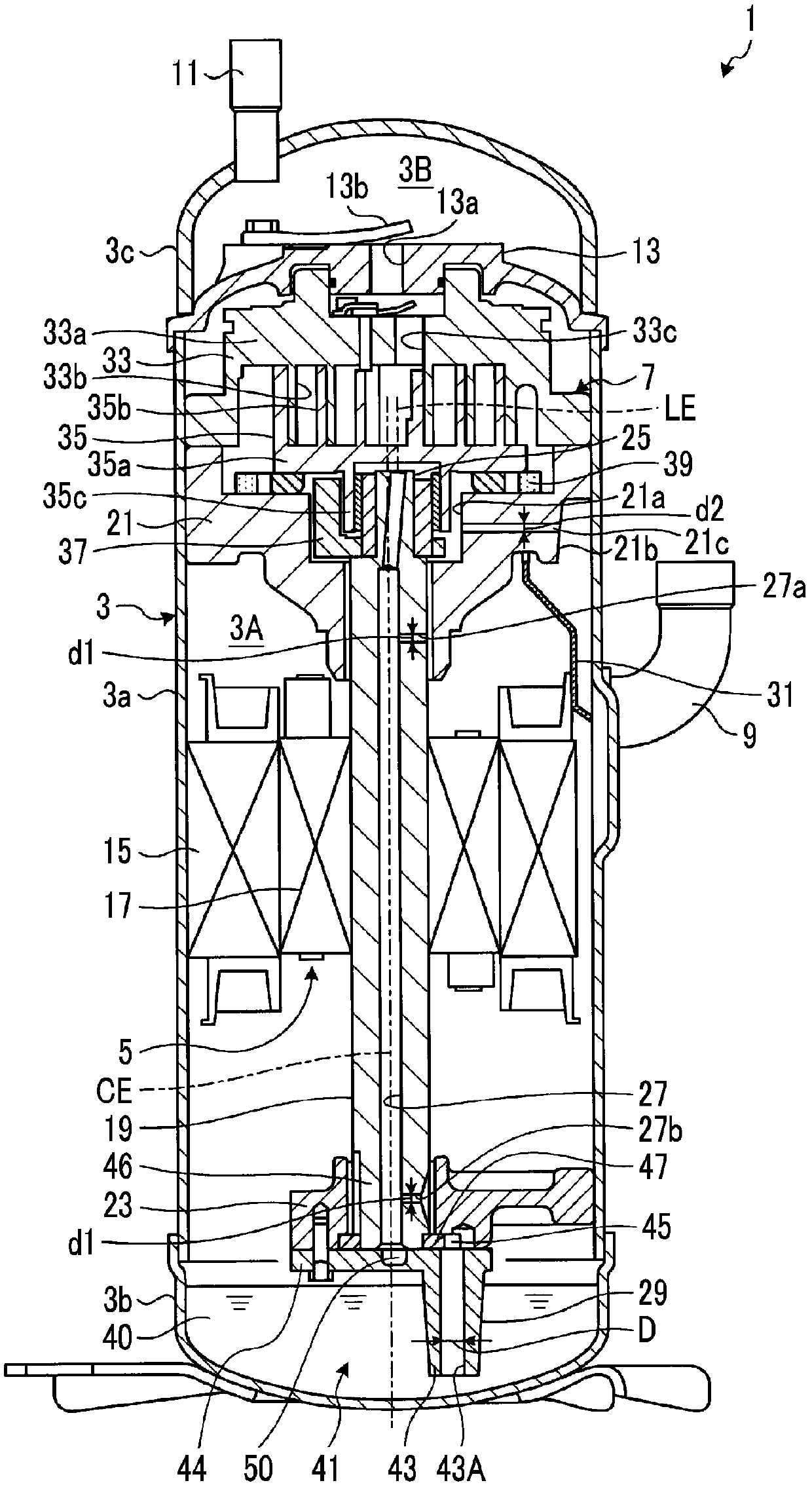
[0025] figure 1 It is an overall sectional view of the scroll compressor according to the present embodiment. The scroll compressor 1 compresses and sucks in a fluid (for example, refrigerant) and discharges it. In the present embodiment, the scroll compressor 1 is interposed in a refrigerant flow path that circulates the refrigerant in an air conditioner, refrigeration device, or the like.

[0026] Such as figure 1 As shown, the scroll compressor 1 includes a motor (drive motor) 5 as a drive configuration and a scroll compression mechanism 7 driven by the motor 5 inside a casing 3 .

[0027] The casing 3 ha...


PUM


Abstract

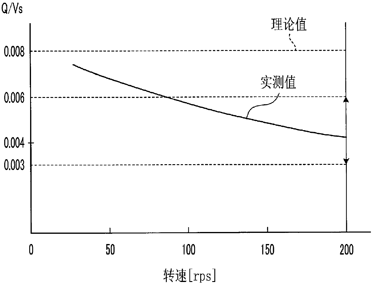
A scroll compressor is equipped with: a scroll compression mechanism that is housed in a housing and compresses a low-pressure gas; a motor that is linked to the scroll compression mechanism by a rotary shaft and that drives the scroll compression mechanism; an upper bearing and a lower bearing that support the rotary shaft in a rotatable manner; and an oil supply pump that draws in lubricating oil due to the rotation of the rotary shaft and supplies the lubricating oil to sliding parts. The oil supply pump is a positive-displacement pump which is capable of operating in an operating region wherein the rotational frequency of the motor is 150 rps or higher, and for which an inclination indicating the rate of increase in the amount of oil supplied per unit time with respect to the rotational frequency decreases as the rotational frequency increases.

Description

technical field [0001] The present invention relates to a scroll compressor used in refrigeration equipment, air conditioning equipment and the like. Background technique [0002] Generally, a scroll compressor including a scroll compression mechanism accommodated in a housing and a drive motor for driving the scroll compression mechanism is widely known. The scroll compression mechanism is configured to include a fixed scroll member and an orbiting scroll member provided with a spiral wrap on one side of a disk-shaped end plate, and the fixed scroll and the orbiting scroll The disks face each other while meshing with the scroll, and the orbiting scroll performs orbital motion relative to the fixed scroll. Then, the volume of the compression space formed between both wraps is reduced as the orbiting scroll turns, thereby compressing the fluid (gas refrigerant) in the space. [0003] In the scroll compressor, it is necessary to lubricate each sliding part for the purpose of...

Claims


Application Information

Patent Timeline
Patent Type & Authority Patents(China)
IPC IPC(8): F04C18/02F04C29/02
CPCF04C18/0215F04C23/008F04C29/025F04C29/028
Inventor 谷口征大木全央幸佐藤创高须洋悟堀田阳平馆石太一山下拓马金井晖裕
Owner MITSUBISHI HEAVY IND THERMAL SYST
Learn More