Ice-storage heat pump energy saving unit

An energy-saving unit and ice storage technology, applied in heat pumps, heating and cooling combinations, refrigerators, etc., can solve problems such as energy consumption, waste of energy and resources, and reduced operating efficiency, and achieve the effect of avoiding pollution

Active Publication Date: 2006-04-26
中碳实业(珠海)有限公司
View PDF0 Cites 11 Cited by
  • Summary
  • Abstract
  • Description
  • Claims
  • Application Information

AI Technical Summary

Problems solved by technology

However, the existing ice-storage air conditioners have the following disadvantages: because the temperature of the chilled water is lower than that of conventional air conditioners, the evaporation temperature of the refrigerant (refrigerant) is lowered, and compared with conventional air conditioners, the compressor runs at a lower temperature, making it run At the same time, due to the lower operating temperature of the ice storage system, the rated capacity of the compressor is also increased, that is, the power consumption for obtaining unit cooling capacity is correspondingly increased
[0004] At present, many hotels, hotels, restaurants, saunas, swimming pools and other construction places require hot water for production, life and sanitation, which are generally produced by traditional heating equipment such as coal-fired, oil-fired boilers or electric boilers, thus consuming a large amount of water. energy; while the chillers of the central air conditioner also produce a large amount of waste heat when cooling. This waste heat is carried by high-temperature, high-pressure refrigerant and discharged into the outdoor air through the cooling tower. severe thermal pollution of the air
It can be seen that in some occasions that both refrigeration and a large amount of hot water are required, a large amount of heat energy is wasted in the refrigeration process, while the process of generating hot water needs to consume additional fuel to generate heat energy, resulting in a double waste of energy and resources. , which is neither economical nor polluting the environment, people have deeply realized the necessity and urgency of saving energy and reducing consumption
[0005] Therefore, the existing products have the following deficiencies: low operating efficiency of the compressor, waste of energy and resources, inability to recycle and fully utilize the waste heat of the chiller, and high comprehensive operating costs

Method used


Image

  • Ice-storage heat pump energy saving unit
  • Ice-storage heat pump energy saving unit
  • Ice-storage heat pump energy saving unit

Examples


Embodiment Construction

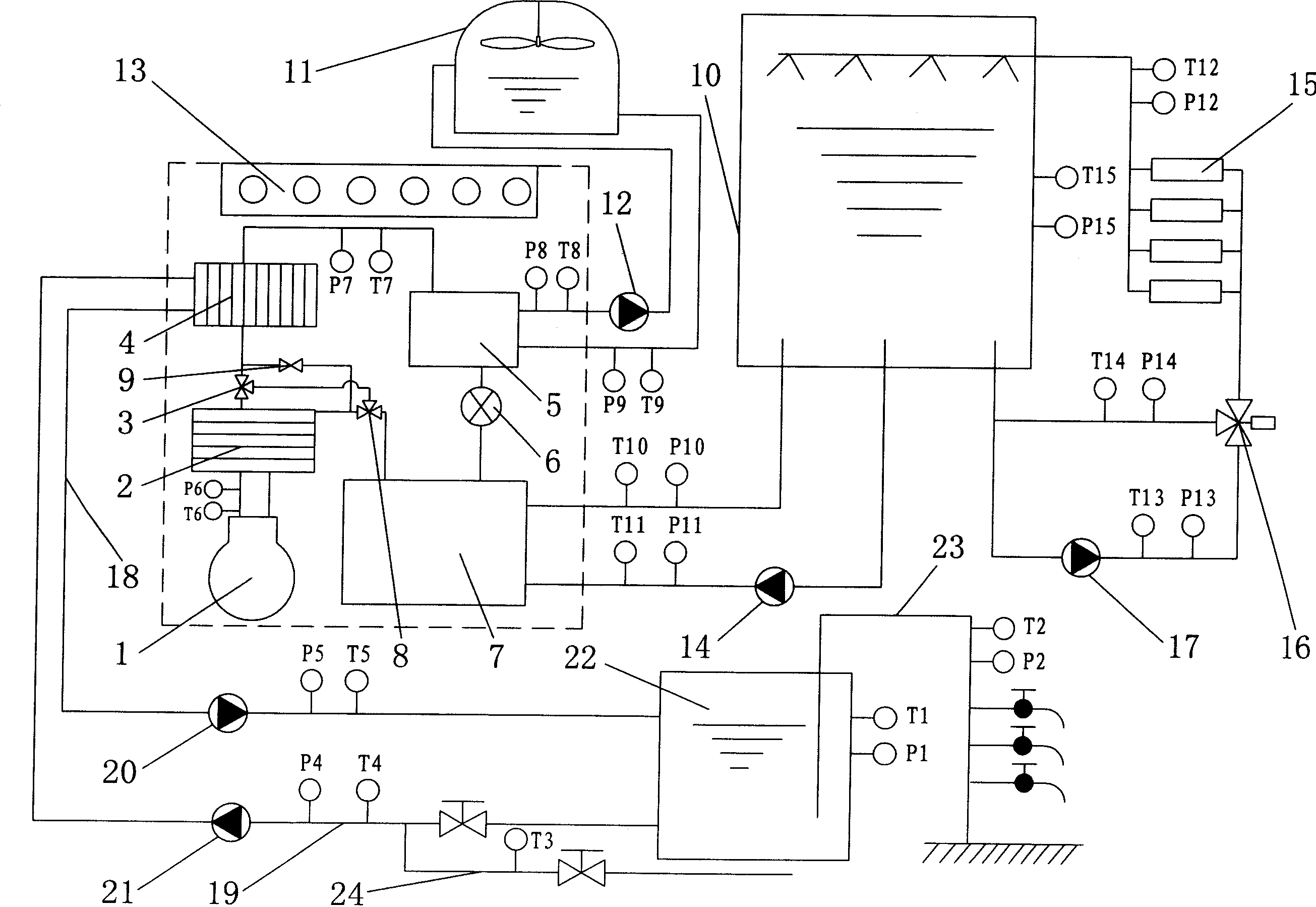
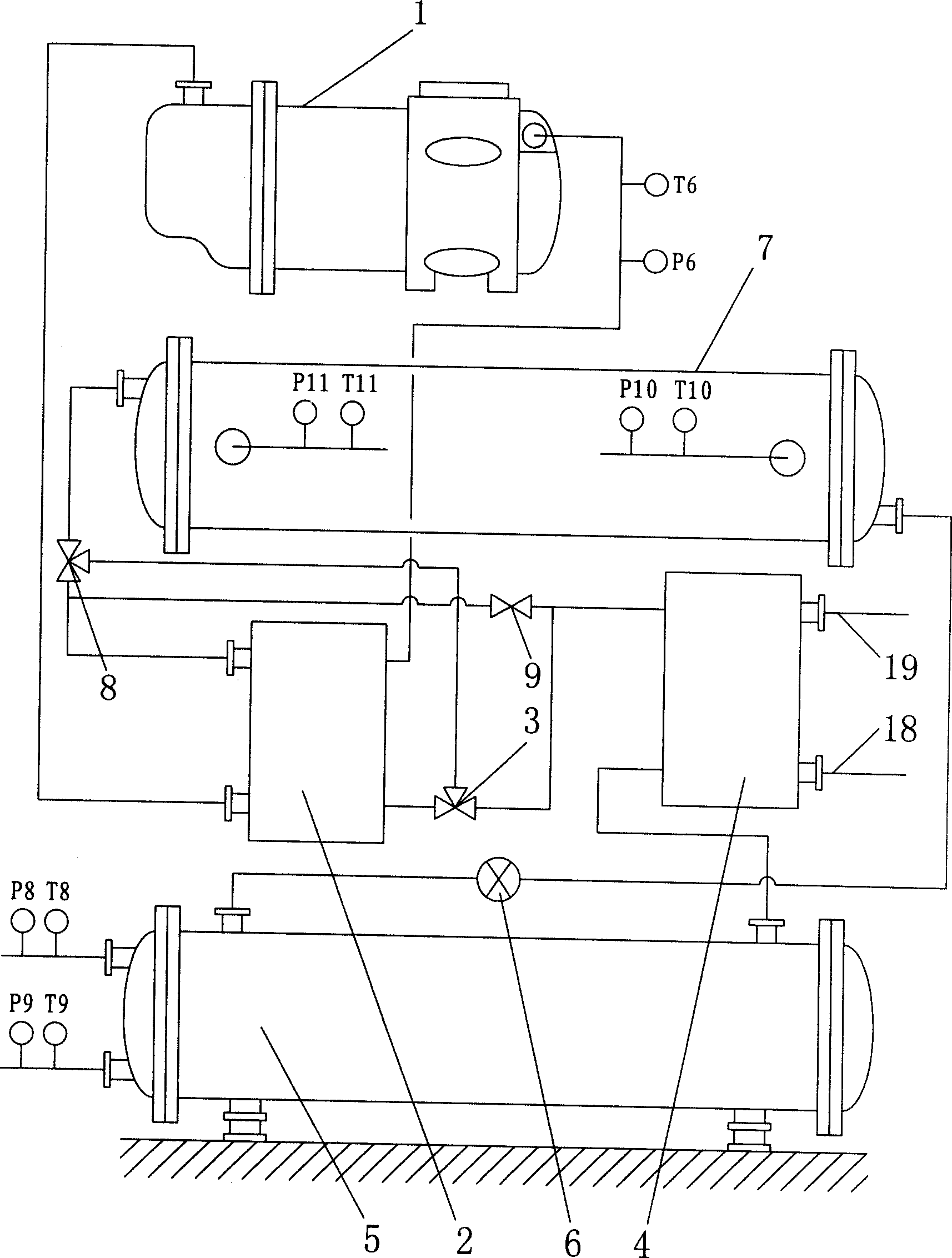
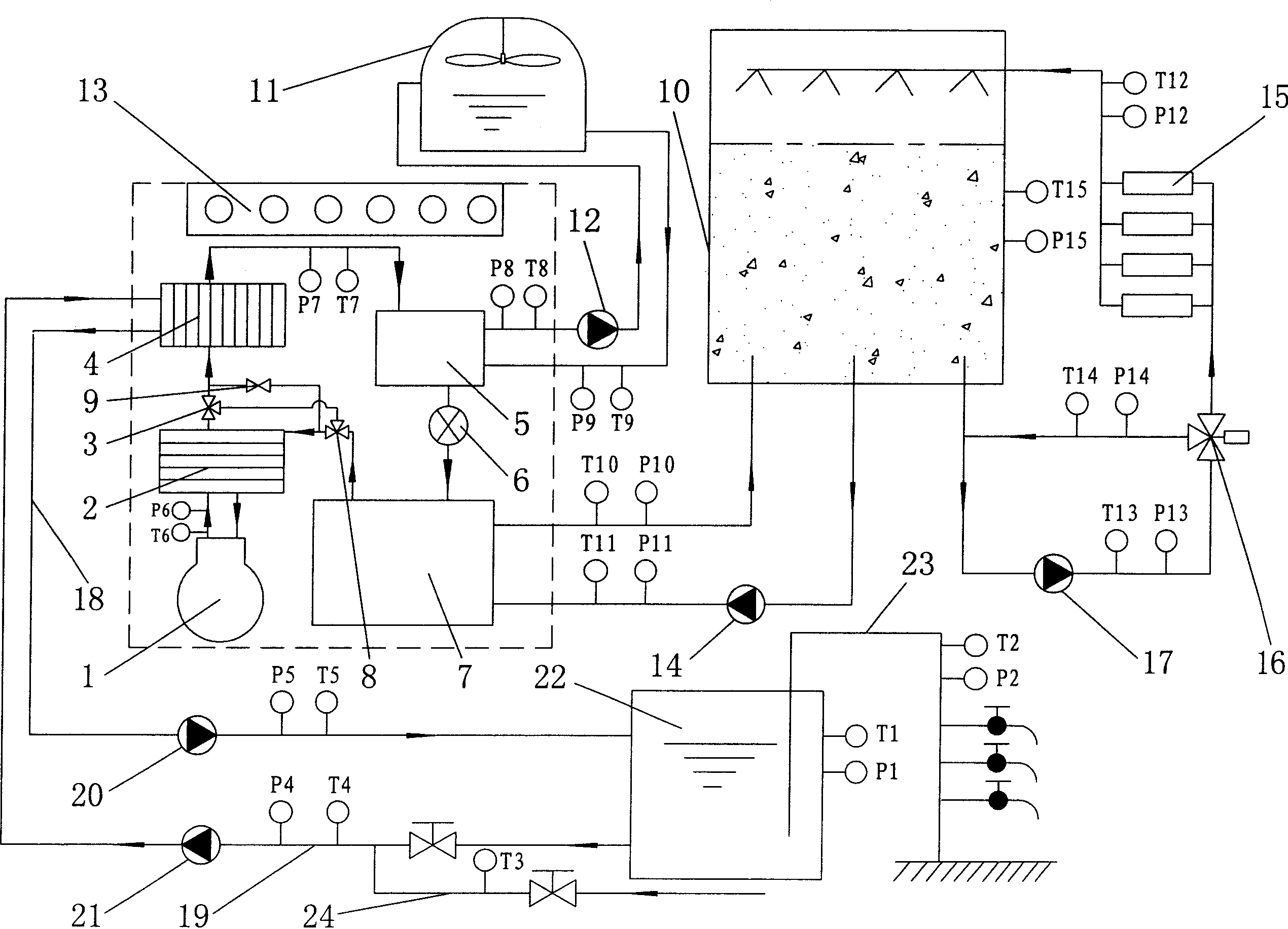
[0017] Such as figure 1 , figure 2 , image 3 , Figure 4As shown, the present invention includes a water chiller, a refrigerant cooling water circulation system, an ice storage system, an indoor cooling and heating system, a hot water circulation system, a user hot water system, a computer automatic control device 13, and a cold water supply pipe 24. The water chiller includes compressor 1, plate refrigerant heat exchanger 2, plate refrigerant-water heat exchanger 4, I heat exchanger 5, electronic expansion valve 6, II heat exchanger 7 and passes through the refrigerant in turn The pipelines are connected to form a circulation loop. The chiller also includes an I electronic three-way valve 3, an II electronic three-way valve 8, and a solenoid valve 9. The hot side of the plate refrigerant heat exchanger 2 is connected to the The refrigerant pipeline between the compressor 1 outlet and the I heat exchanger 5, and the cold side is connected to the refrigerant pipeline betwe...


PUM


Abstract

The invention discloses an ice-reservation heat pump energy-saving unit, which comprises the following parts: cold water unit, refrigerating working fluid cooling water circulation system, ice-reservation system, indoor cold-and-heat supply system and computer self-control device (13), wherein the cold water unit contains compressor (1), first heat-exchanger (5), electronic expansion valve (6), second heat-exchanger (7), plate-type refrigerating working fluid heat-exchanger (2), first electronic three-way valve (3), second electronic three-way valve (8), electromagnetic valve (9), which forms a loop through refrigerating working fluid pipe connection. The invention can be applied in the air-conditioner energy-saving domain widely.

Description

technical field [0001] The invention relates to an ice storage heat pump energy-saving unit. Background technique [0002] Air-conditioning energy storage technology is a practical and comprehensive technology that has emerged in China since the 1990s. It can shift peaks and fill valleys in the power grid, which is conducive to the optimal allocation of social resources. At the same time, due to the peak and valley electricity prices The air-conditioning energy storage technology has greatly reduced the operating electricity cost of the user, so it is a technology that benefits the country and the people. Energy-storage air conditioners use energy-storage equipment to store energy when the air-conditioning system does not need energy or use little energy, and release this part of energy when the air-conditioning system requires a lot of energy. According to the object of use and the level of storage temperature, it can be divided into cold storage an...

Claims


Application Information

Patent Timeline
Patent Type & Authority Applications(China)
IPC IPC(8): F25B29/00F24F5/00F25B30/02
Inventor 聂民
Owner 中碳实业(珠海)有限公司
Why Eureka
Try Eureka