Plate drilling device

A drilling device and plate technology, applied in positioning devices, feeding devices, boring/drilling, etc., can solve the problems of plate surface scratches, plate drilling rig safety hazards, operator injuries, etc., to achieve stable operation, Prevents scratches on the surface of the board and has a high safety effect

Inactive Publication Date: 2018-03-30
CIXI XINCHANG IND PROD DESIGN
View PDF9 Cites 2 Cited by
  • Summary
  • Abstract
  • Description
  • Claims
  • Application Information

AI Technical Summary

Problems solved by technology

[0002] Plates are available in various industries. When the plates are used, they often need to be drilled according to the needs. When drilling, generally clamps are required to fix the plates, so as to prevent shaking or sliding during drilling. Then start the motor that drives the drilling tool, and move the drilling tool towards the plate, but in the traditional drilling machine, the drilling tool is generally exposed, and it is easy to cause damage to the surface of the plate when the plate is advanced. scratches, and in the process of fixing the plate, if the motor is accidentally started, it is easy to cause injury to the operator. Therefore, the traditional plate drilling machine has potential safety hazards

Method used


Image

  • Plate drilling device
  • Plate drilling device
  • Plate drilling device

Examples


Embodiment Construction

[0019] All the features disclosed in this specification, or all disclosed methods or steps in the process, except for mutually exclusive features and / or steps, can be combined in any manner.

[0020] Any feature disclosed in this specification (including any appended claims, abstract and drawings), unless specifically stated, can be replaced by other equivalent or equivalent alternative features. That is, unless otherwise stated, each feature is just one example of a series of equivalent or similar features.

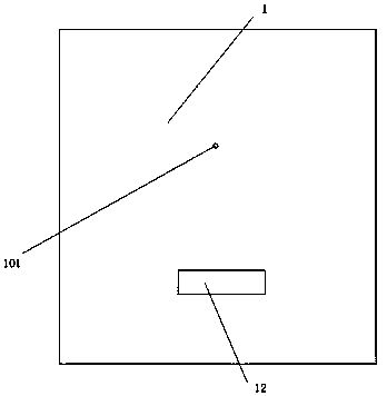
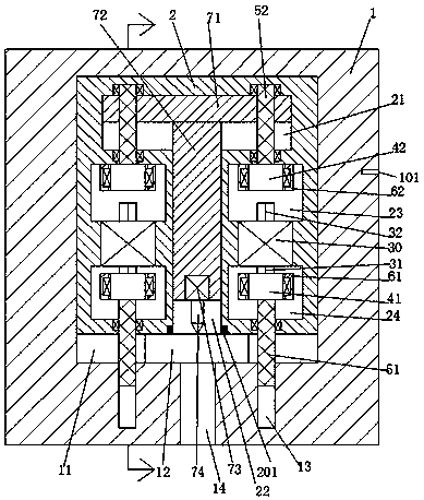
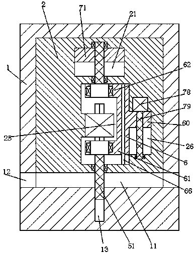
[0021] Such as Figure 1-3 As shown, a plate drilling device of the present invention includes a body 1 in which a sliding cavity 11 is provided, and a sliding frame body 2 is slidably installed in the sliding cavity 11 up and down, and the sliding frame body 2 A first sliding groove 22 with an opening facing downward is provided in the center, and a second sliding groove 21 communicating with the first sliding groove 22 is provided in the sliding frame body 2 at the upper e...


PUM


Abstract

The invention provides a plate drilling device. The plate drilling device comprises a machine body, wherein a sliding cavity is formed in the machine body, and a sliding frame body is arranged in thesliding cavity in an up-and-down sliding mode. A first sliding groove with a downward opening is formed in the center of the sliding frame body, a second sliding groove communicating with the first sliding groove is formed in the upper end of the first sliding groove and in the sliding frame body, a linkage plate is arranged in the second sliding groove in an up-and-down sliding mode, a lifting strip is arranged in the first sliding groove in an up-and-down sliding mode, and the upper end of the lifting strip is fixedly connected with the linkage plate. The lower end of the lifting strip is fixedly provided with a drilling motor, the lower end of the drilling motor is in power connection with a drilling tool, an upper mounting groove and a lower mounting groove are symmetrically formed inthe left side and the right side of the sliding frame body, a conversion motor is fixedly arranged between the upper mounting groove and the lower mounting groove, the upper end and the lower end of the conversion motor are in power connection with an upper power shaft and a lower power shaft respectively, and a communication groove for communicating the upper mounting groove and the lower mounting groove is formed in the portion between the upper mounting groove and the lower mounting groove and at the rear end of the conversion motor.

Description

Technical field [0001] The invention relates to the field of plate processing machinery, in particular to a plate drilling device. Background technique [0002] Plates are available in various industries. When the plates are used, they often need to be drilled according to their needs. During drilling, clamps are generally required to fix the plates to prevent shaking or sliding during drilling. Then start the motor that drives the drilling tool and move the drilling tool toward the plate. However, in traditional drilling rigs, the drilling tool is generally exposed, which is likely to cause damage to the surface of the plate when the plate is advanced. In the process of fixing the plate, if the motor is accidentally started, it is easy to cause injury to the operator. Therefore, the traditional plate drilling rig has safety hazards. Summary of the invention [0003] The purpose of the present invention is to provide a plate drilling device and a method of use thereof, which can ...

Claims


Application Information

Patent Timeline
IPC IPC(8): B23B39/00B23B47/20B23Q3/00
CPCB23B39/00B23Q3/002B23Q5/40
Inventor 董晨
Owner CIXI XINCHANG IND PROD DESIGN
Why Eureka
Try Eureka