Automatic lateral surface grinding device

An automatic, movable seat technology, used in grinding machines, grinding/polishing equipment, machine tools suitable for grinding workpiece planes, etc., can solve problems such as low grinding efficiency

Pending Publication Date: 2018-03-30
SUZHOU SUZHU HEAVY IND
View PDF0 Cites 9 Cited by
  • Summary
  • Abstract
  • Description
  • Claims
  • Application Information

AI Technical Summary

Problems solved by technology

[0003] The technical problem to be solved by the present invention is to provide an automatic side grind

Method used


Image

  • Automatic lateral surface grinding device
  • Automatic lateral surface grinding device
  • Automatic lateral surface grinding device

Examples


Embodiment Construction

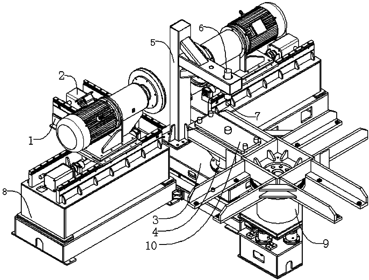
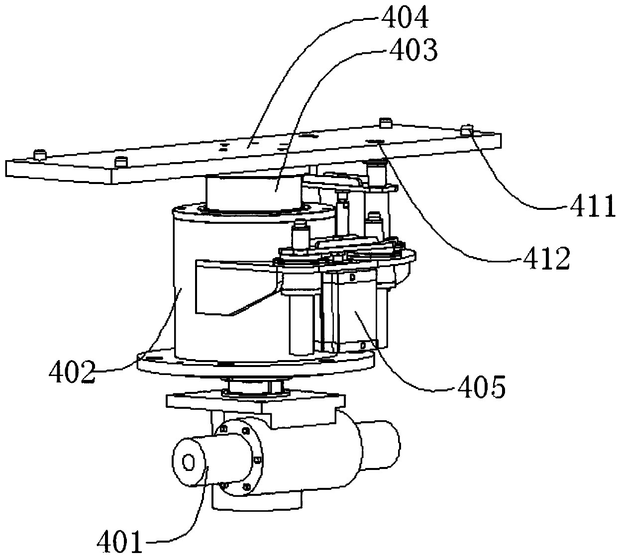
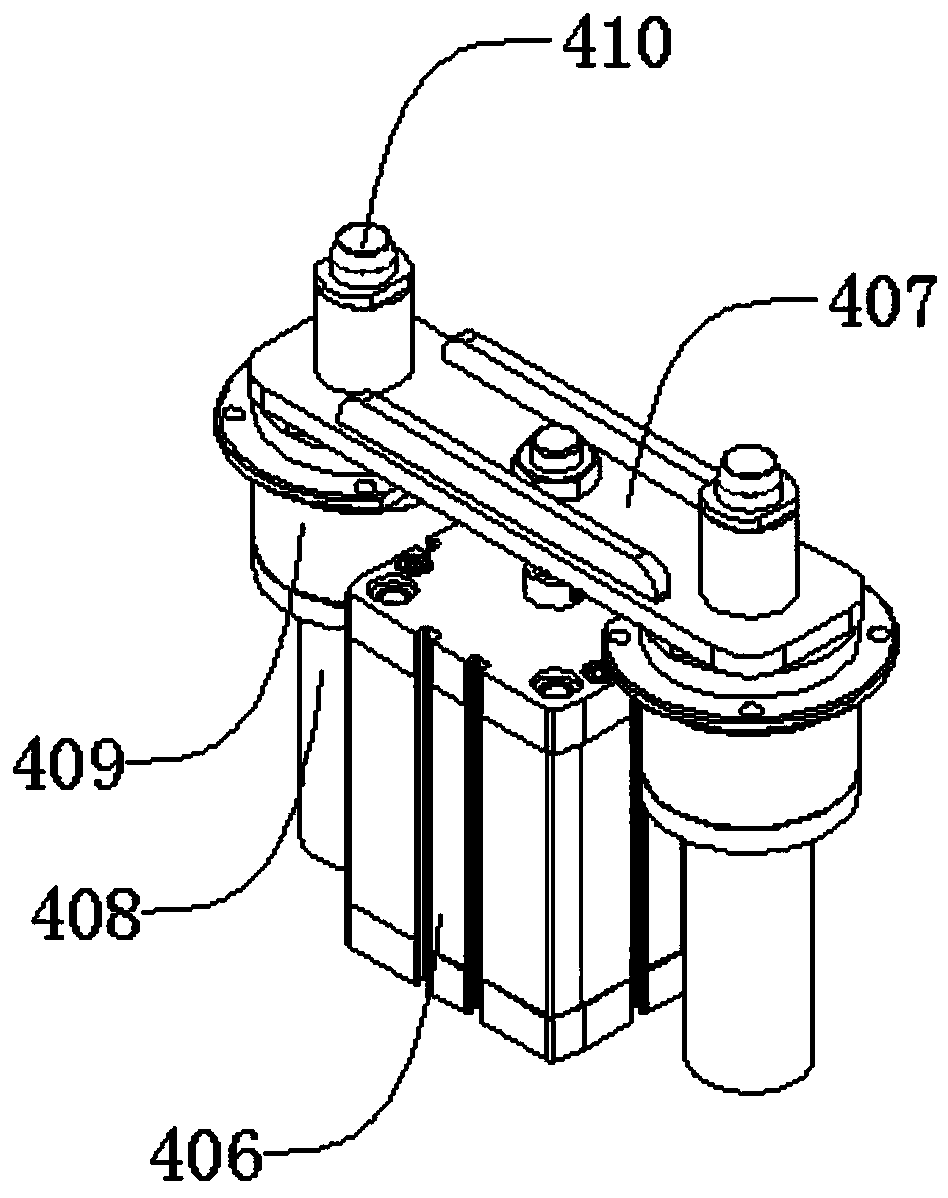
[0023] Such as figure 1 , figure 2 , image 3 , Figure 4 , Figure 5 , Figure 6 , Figure 7As shown, a side automatic grinding device includes a first base 1, a first linear module 2, a moving seat 3, a rotary positioning mechanism 4, a door frame 5, a pressing cylinder 6, a pressure head 7, a grinding mechanism 8, Rotary feeding mechanism 9, combined pallet 10, the first linear module 2 is located at the upper end of the first base 1, the first linear module 2 is connected with the first base 1 by bolts, the moving The seat 3 is located at the upper end of the first linear module 2 and at the upper end of the first base 1, the moving seat 3 is connected with the first linear module 2 by bolts, and the moving seat 3 can be moved left and right along the first base 1. Sliding, the described rotary positioning mechanism 4 is located at the upper end of the mobile seat 3, the described rotary positioning mechanism 4 is connected with the mobile seat 3 by bolts, the descr...


PUM


Abstract

The invention discloses an automatic side grinding device, which comprises a first base, a first linear module, a moving seat, a rotary positioning mechanism, a door frame, a downward pressure oil cylinder, a pressure head, a grinding mechanism, a rotary feeding mechanism, and a combined pallet , first place the combined pallet on the upper end of the two adjacent rail frames, place the casting on the combined pallet, when the rotary feeding mechanism rotates to a set angle, the first linear module drives the moving seat to drive the rotary positioning mechanism to move To the right below the combined pallet, lift the oil cylinder back, so that the combined pallet completely falls on the upper end of the rotary positioning mechanism, the first linear module drives the moving seat to reset, the positioning mechanism works to fix the combined pallet, and the downward pressure cylinder pushes the pressure head Press the casting down for grinding. The structure of the device is simple, and it only needs to place the castings on the combination pallet for automatic continuous feeding, and a rotating positioning mechanism is designed to rotate the castings 90°, so as to automatically polish the four sides of the castings, effectively improving production efficiency.

Description

technical field [0001] The invention relates to a mechanical device, in particular to an automatic side grinding device. Background technique [0002] The cylinder block is one of the important components of the automobile engine. At present, most of the engine cylinder blocks are produced by casting. After pouring, there will be a lot of flashes and pouring risers on the surface of the engine block. These flashes must be removed. Edges and risers, for iron castings, are usually directly knocked off with an oil hammer, while steel castings need to be cut off by gas cutting, and then the remaining flashes and risers on the castings are polished by a casting grinder, making them smooth and beautiful . At present, the engine block grinding process is not highly automated. When grinding, each side of the engine block is often polished sequentially, which takes a long time and is inefficient. In view of the above defects, it is necessary to design a side automatic grinding devi...

Claims


Application Information

Patent Timeline
IPC IPC(8): B24B7/17
CPCB24B7/17
Inventor 余自马田厚
Owner SUZHOU SUZHU HEAVY IND
Why Eureka
Try Eureka