
Indoor wallboard capable of being dismounted and mounted

An indoor wall panel, dismantling technology, applied in the direction of walls, building components, buildings, etc., can solve the problems of high cost, inconvenience, time-consuming and laborious dismantling, etc., to increase the opportunity for recycling, increase the use function, and avoid excessive damage. Effect

Pending Publication Date: 2018-03-30
大美砼艺(天津)建筑科技发展有限公司
View PDF8 Cites 8 Cited by
  • Summary
  • Abstract
  • Description
  • Claims
  • Application Information

AI Technical Summary

Problems solved by technology

In the prior art, commonly used partition walls include: brick interior partition walls, aerated concrete block interior partition walls, lightweight small blocks, gypsum hollow strip partition walls, etc., and there are the following problems: first, these interior partition walls Wet work is required, the labor intensity of masonry is relatively high, and it takes a long construction period, requiring skilled workers, high cost, and time-consuming and laborious demolition, which is very inconvenient
", so as to achieve the purpose of easy disassembly; but the interior wall panel is prepared in advance, and its function is difficult to change unless it is done again, and when the interior wall panel is combined with multiple panels, the end of the wall panel The fixed structure will play a hindering role in the composite process, so that the inner wall panel cannot achieve the purpose of multiple composite composite internal partition walls

Method used


Image

  • Indoor wallboard capable of being dismounted and mounted
  • Indoor wallboard capable of being dismounted and mounted
  • Indoor wallboard capable of being dismounted and mounted

Examples


Embodiment Construction

[0041] First of all, it should be noted that the specific structures, features and advantages of the present invention will be described in detail below by way of examples, but all descriptions are for illustration only, and should not be construed as forming any limitation on the present invention . In addition, any single technical feature described or implied in each embodiment mentioned herein, or any single technical feature shown or implied in each drawing, can still be described in these technical features (or their equivalents) ) to continue any combination or deletion, so as to obtain more other embodiments of the present invention that may not be directly mentioned herein. In addition, for the sake of simplifying the drawings, the same or similar technical features may only be marked in one place in the same drawing.

[0042] It should be noted that the terminology used here is only for describing specific implementations, and is not intended to limit the exemplary ...


PUM


Abstract

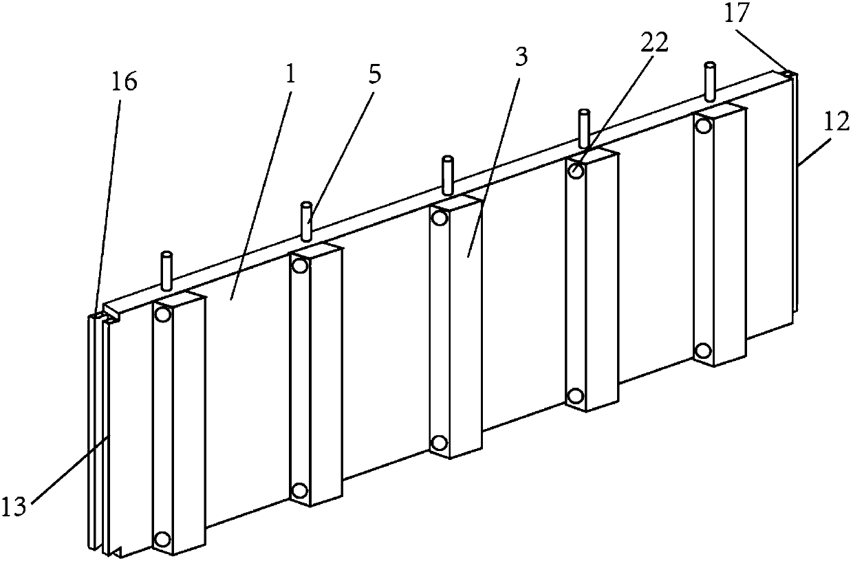
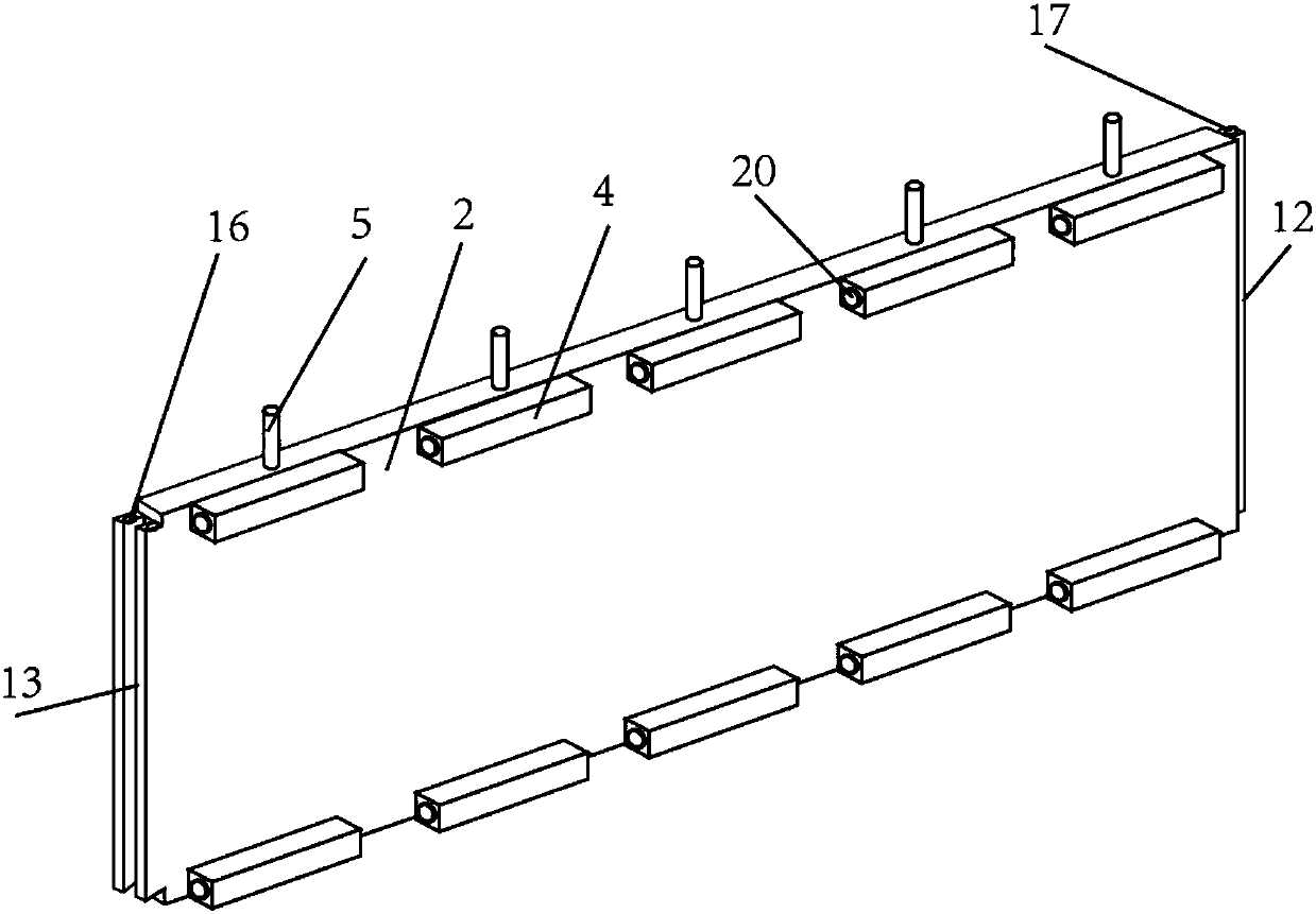
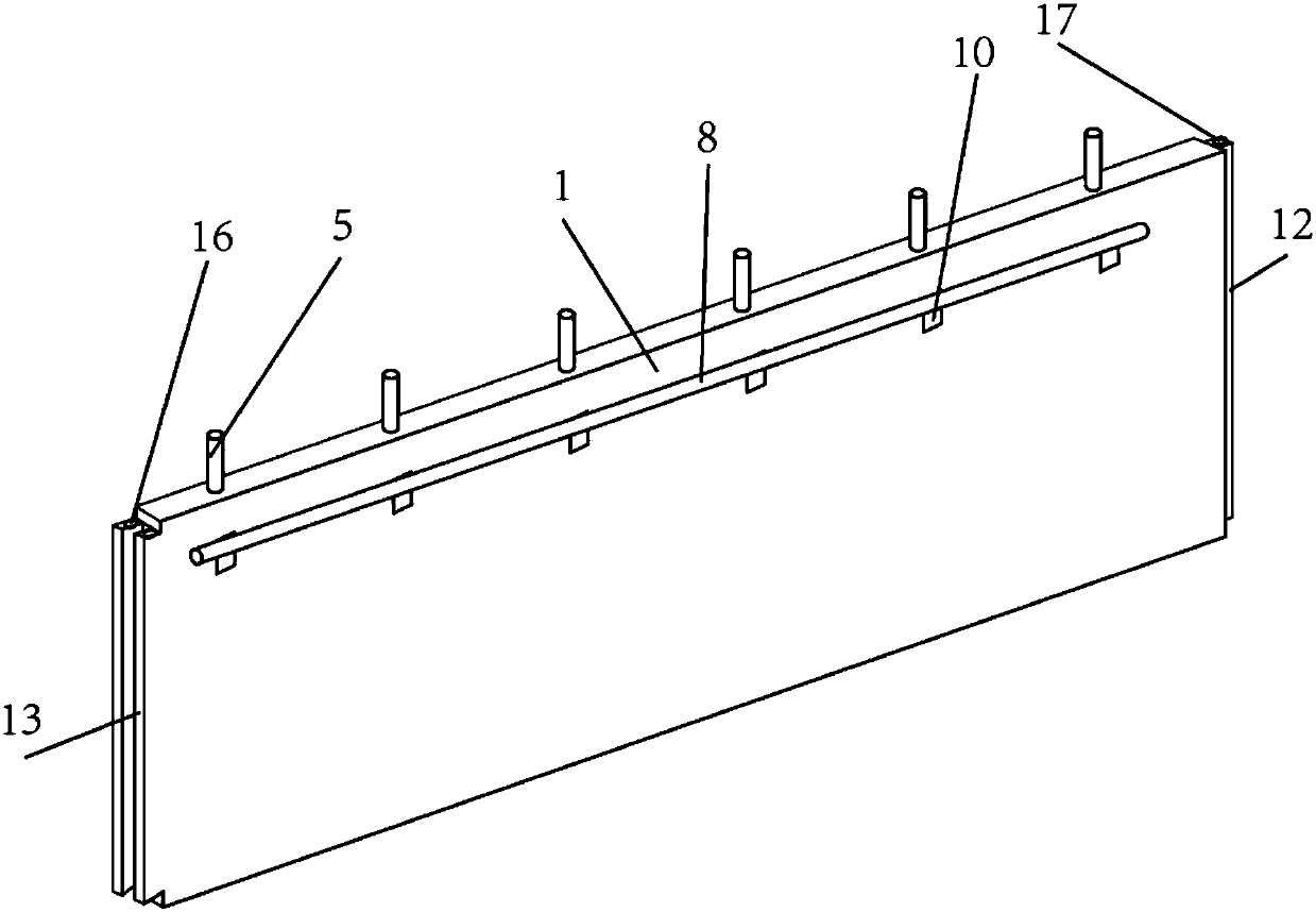
The invention relates to an indoor wallboard capable of being dismounted and mounted. A plurality of first reinforcing ribs are vertically arranged on a first wallboard body, two rows of second reinforcing ribs are horizontally arranged on a second wallboard body, and the second reinforcing ribs can be embedded into the positions between every two adjacent first reinforcing ribs through a first fixing mechanism; a plurality of second fixing mechanisms are arranged at each of the tops and the bottoms of the first wallboard body and the second wallboard body correspondingly, the second fixing mechanisms comprise fixing blocks, base plates, connecting rods and handles, and first grooves are formed in the first wallboard body and the second wallboard body correspondingly; open holes in the vertical direction are formed in the side walls of the first grooves, one ends of the connecting rods are fixedly arranged in the middles of the bottom faces of the base plates, and the other ends of theconnecting rods extend out of the open holes, and are fixedly connected with the handles; and the four corners of the bottom face of every base plate are fixedly connected with the bottom faces of the first grooves through first springs, and a boss and a concave body which can be matched with each other are arranged at the two ends of each of the first wallboard body and the second wallboard bodycorrespondingly. According to the indoor wallboard capable of being dismounted and mounted, dismounting and mounting are convenient, a plurality of inner wallboards can be combined with one another in the length direction, and filling materials with different functions can be changed in a wall.

Description

technical field [0001] The invention belongs to the technical field of indoor wall panels, in particular to a detachable indoor wall panel. Background technique [0002] The wall is an important part of the building, and its function is to bear the load, enclose or separate the space; it can be divided into load-bearing walls and non-load-bearing walls according to the stress situation and materials; any wall that directly bears the load transmitted from the upper roof and floor It is called load-bearing wall; any wall that does not bear the upper load is called non-load-bearing wall; non-load-bearing wall includes partition wall and filling wall. The partition wall plays the role of separating the indoor space, and should meet the requirements of sound insulation and fire prevention, and its weight is borne by the floor or beam; the filling wall is generally filled between the column walls of the frame structure. [0003] At present, almost every house has to be renovated,...

Claims


Application Information

Patent Timeline
IPC IPC(8): E04B2/74
CPCE04B2/74
Inventor 朱万银
Owner 大美砼艺(天津)建筑科技发展有限公司
Learn More