Developing box

A technology of developing box and moving rod, applied in the field of developing box, can solve the problems of falling off of power receiving parts, and achieve the effect of preventing falling off

Pending Publication Date: 2018-03-30
ZHUHAI TUOJIA TECH
View PDF0 Cites 12 Cited by
  • Summary
  • Abstract
  • Description
  • Claims
  • Application Information

AI Technical Summary

Problems solved by technology

[0005] Existingly, the component that the developing cartridge receives the driving force from the equipment is a power receiving part called a universal joint, one end of the power receiving part is installed on the developing cartridge, and the other end is connected with the power in the equipment. The output member combines and receives the driving force output by the power output member. One end of the power receiving member installed in the developing cartridge can rotate freely around its axis of rotation, that is to say, the combination of the power receiving member and the developing cartridge is not tight fit. During the entire life cycle of the cartridge, the power receiving member needs to be continuously combined and disengaged from the power output member. During such a large movement, the power receiving member has the risk of falling out of the developing cartridge

Method used


Image

  • Developing box
  • Developing box
  • Developing box

Examples


Embodiment Construction

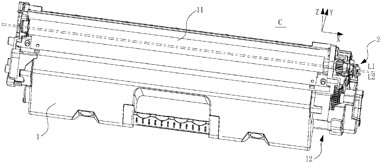
[0037] Embodiments of the present invention will be described in detail below in conjunction with the accompanying drawings. First, define: the longitudinal direction of the developing cartridge is longitudinal X, the installation direction of developing cartridge is horizontal Y, and the direction perpendicular to the longitudinal X and horizontal Y is vertical Z.

[0038] figure 1 It is a schematic diagram of the overall structure of the developing cartridge involved in the present invention.

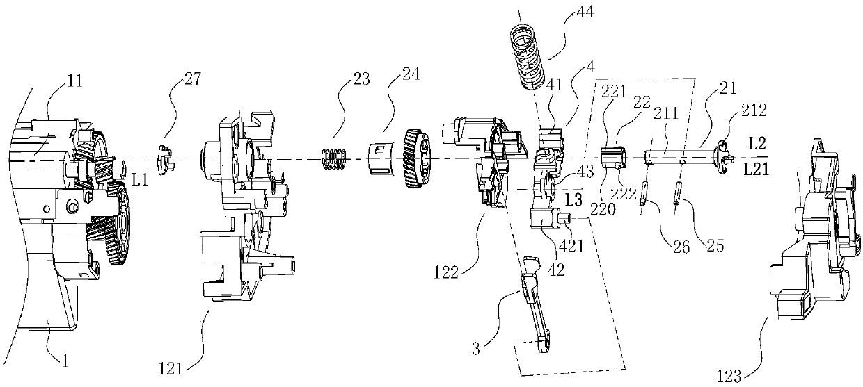
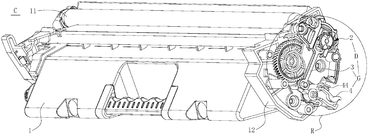
[0039] The developing cartridge C is detachably installed in a device with a power output, including a housing 1, a rotating member 11 rotatably installed in the housing, an end cover assembly 12 installed on the housing, and a longitudinal The driving assembly D at the end, the driving assembly D includes a power transmission device 2 installed in the developing cartridge and a moving rod assembly G combined with the power transmission device 2, and the power transmission device 2 is...


PUM


Abstract

The invention relates to a developing box, which comprises a shell, an end cover assembly arranged on the shell, and a drive assembly located at one longitudinal tail end of the shell. The drive assembly comprises a power transmission device arranged in the developing box and a motion rod assembly combined with the power transmission device; the motion rod assembly comprises a first motion rod anda second motion rod in a mutually combined mode; the first motion rod is combined with the power transmission device; the end cover assembly comprises a first end cover fixedly connected with the shell and a second end cover fixedly arranged on the first end cover; the second end cover comprises a second end cover body, and a through hole and a second guiding part arranged on the second end coverbody; the power transmission device penetrates through the through hole; the first motion rod is guided by the second guiding part.

Description

technical field [0001] The invention relates to the field of electrophotographic imaging, in particular to a developing box detachably installed in an electrophotographic imaging device. Background technique [0002] Commonly used electrophotographic imaging equipment (hereinafter referred to as "equipment"), such as printers, copiers, etc., use a laser beam loaded with target information to scan the surface of the photosensitive element to form an electrostatic latent image on the surface of the photosensitive element, and the surface is coated with a developer. The developing part is close to the surface of the photosensitive element, and uses the developer to develop the electrostatic latent image, and then the developer is transferred to the imaging medium. [0003] From the perspective of reducing the use cost of the end user, a developing cartridge in which the photosensitive element and the developing member are separately arranged has appeared on the market, that is,...

Claims


Application Information

Patent Timeline
Patent Type & Authority Applications(China)
IPC IPC(8): G03G15/08G03G21/16
CPCG03G15/08G03G21/1647G03G21/1676G03G21/1857G03G2221/1657
Inventor 周欣闻艺俊
Owner ZHUHAI TUOJIA TECH
Why Eureka
Try Eureka