Permanent magnet speed regulator with fixed magnetic gap

A technology of permanent magnet governor and fixed magnet, which is applied in the direction of permanent magnet clutch/brake, control electromechanical brake, electric brake/clutch, etc. It can solve the problems of low torque transmission capacity, consumption, and inability to achieve synchronization, etc., to achieve The effect of speed regulation response is fast, energy saving efficiency is improved, and transmission energy is saved

Pending Publication Date: 2018-03-30
山东洁盟节能环保技术有限公司
View PDF0 Cites 0 Cited by
  • Summary
  • Abstract
  • Description
  • Claims
  • Application Information

AI Technical Summary

Problems solved by technology

However, there is a slip between the input and output, and synchronization cannot be achieved, and the heat generated by the slip is consumed, and the torque transmission capacity is low

Method used


Image

  • Permanent magnet speed regulator with fixed magnetic gap
  • Permanent magnet speed regulator with fixed magnetic gap
  • Permanent magnet speed regulator with fixed magnetic gap

Examples


Embodiment 1

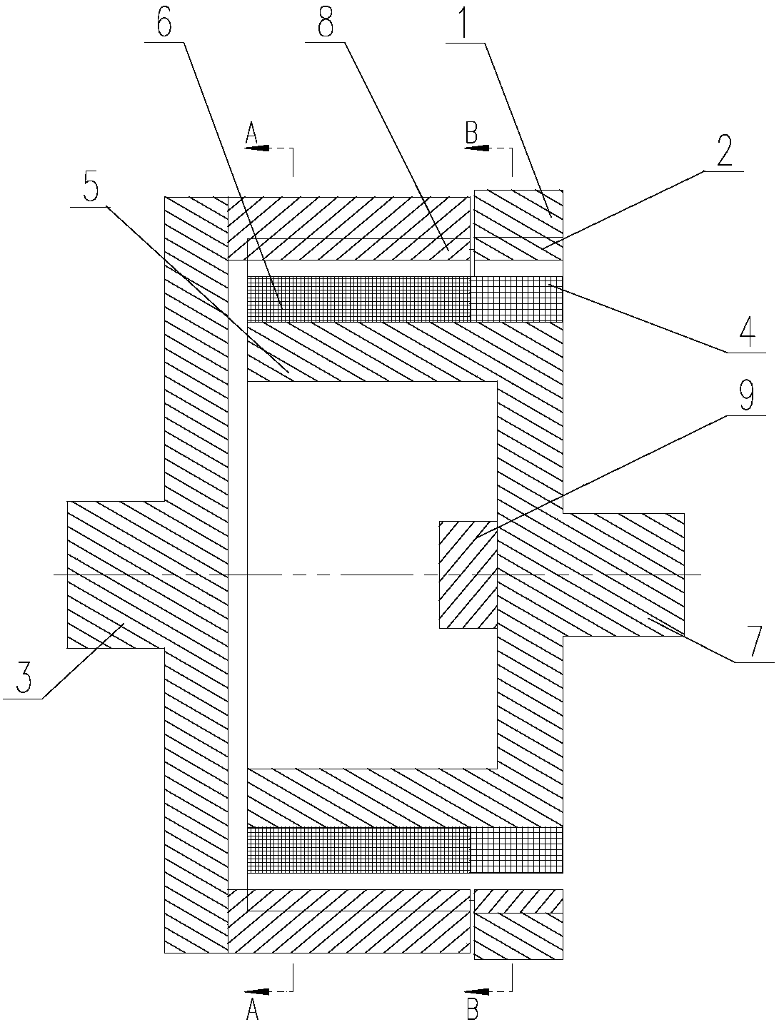
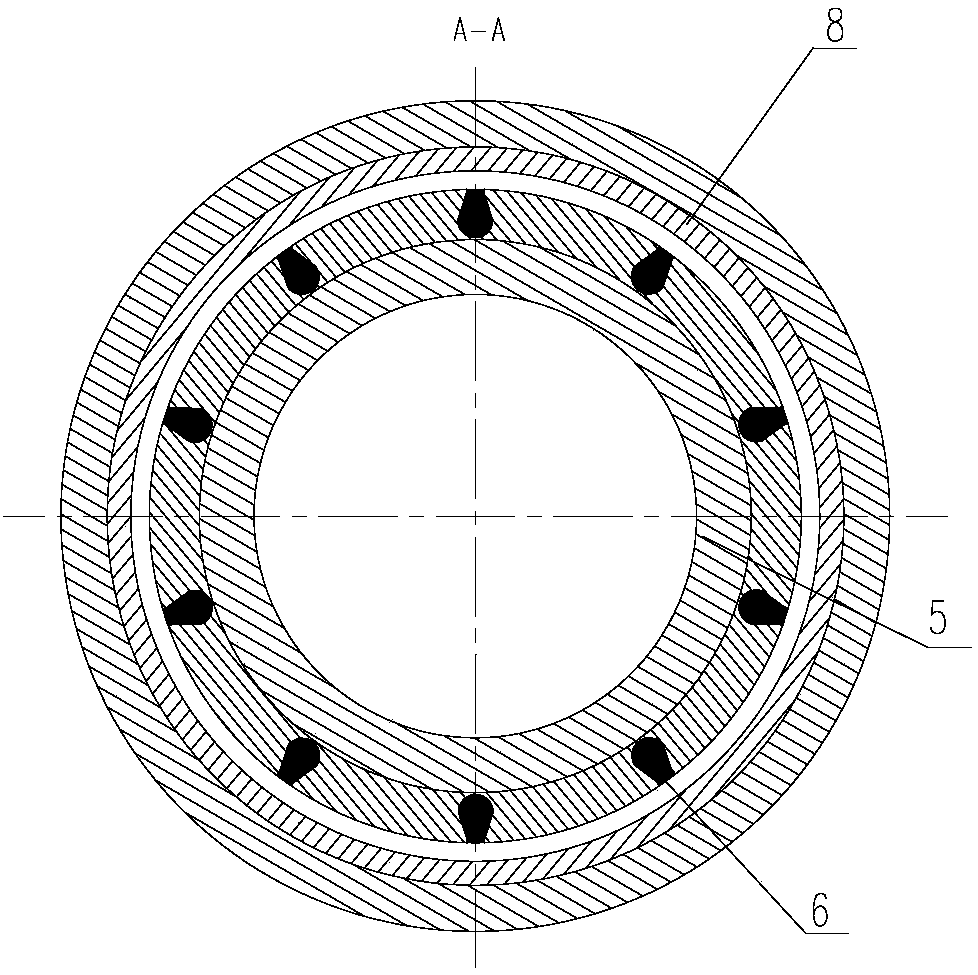
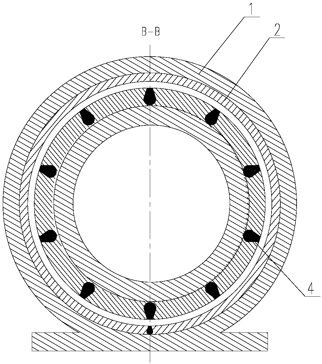
[0021] A permanent magnet governor with a fixed magnetic gap, including a magnetic rotor connected to the input shaft 3, a magnetic stator located at the end of the magnetic rotor and arranged in parallel with the magnetic rotor, and a magnetic rotor connected to the output shaft 7 and located inside the circumference of the magnetic rotor and the magnetic stator. The inner armature rotor; the permanent magnets B 8 distributed circumferentially along the inner circumferential surface of the magnetic rotor; the magnetic stator includes a fixed seat 1 and permanent magnets A 2 distributed circumferentially along the inner circumferential surface of the fixed seat 1 ; The inner armature rotor includes an iron core 5, and a winding coil B 6 and a winding coil A 4 are arranged side by side along the outer circumferential surface of the iron core 5; the winding coil B 6 and the winding coil A 4 are respectively connected with the permanent magnet B8 Corresponding to the permanent mag...

Embodiment 2

[0026]A permanent magnet governor with a fixed magnetic gap, including a magnetic rotor connected to the input shaft 3, a magnetic stator located at the end of the magnetic rotor and arranged in parallel with the magnetic rotor, and a magnetic rotor connected to the output shaft 7 and located inside the circumference of the magnetic rotor and the magnetic stator. The inner armature rotor; the permanent magnets B 8 distributed along the inner circumferential surface of the magnetic rotor; the magnetic stator includes a fixed seat 1 and permanent magnets A 2 distributed along the inner circumferential surface of the fixed seat 1; The inner armature rotor includes an iron core 5, and a winding coil B 6 and a winding coil A 4 are arranged side by side along the outer circumference of the iron core 5; the winding coil B 6 and the winding coil A 4 are respectively connected with the permanent magnets B 8 and The permanent magnet A 2 is arranged correspondingly; the control system 9 f...


PUM


Abstract

The invention relates to a permanent magnet speed regulator with a fixed magnetic gap. The permanent magnet speed regulator comprises a magnetic rotor connected with the input shaft, a magnetic statorarranged at the tail end of the magnetic rotor and arranged parallel to the magnetic rotor, and an inner armature rotor connected with the output shaft and positioned on the circumferential inner sides of the magnetic rotor and the magnetic stator; permanent magnets B are distributed in the circumferential direction of the inner circumferential surface of the magnetic rotor; the magnetic stator comprises a fixed base and permanent magnets A distributed in the circumferential direction of the inner circumferential surface of the fixed base; the inner armature rotor comprises an iron core, anda winding coil B and a winding coil A which are distributed in parallel along the outer circumferential surface of the iron core; and a control system used for electric energy conversion is arranged between the winding coil B and the winding coil A. By adoption of a slip frequency energy rectifying and feedback technology, quick boosting or braking can be realized through the winding coil A, so that the permanent magnet speed regulator with the fixed magnetic gap is quick in response, flexible and stable; and by virtue of the slip frequency energy rectifying and feedback boosting effect, maximum of the speed regulating efficiency is realized consequently.

Description

technical field [0001] The invention relates to a governor, in particular to a permanent magnet governor with a fixed magnetic gap. Background technique [0002] The permanent magnet speed governor uses the magnetic coupling speed of the permanent magnet to realize the soft (magnetic) connection between the motor and the load, without any harmonic generation affecting the power grid, and has high reliability. , Inflammable and explosive, voltage instability and lightning and other harsh environments, greatly reducing mechanical vibration, widely used in electric power, steel, metallurgy, petrochemical, papermaking, municipal, ships, irrigation and mining industries. At present, the commonly used permanent magnet governors realize the speed adjustment by adjusting the air gap. The magnetic circuit regulator consumes a lot of power, and has disadvantages such as poor torque transmission capability, high assembly difficulty, and waste of a large amount of rare earth resources. ...

Claims


Application Information

Patent Timeline
IPC IPC(8): H02K49/10H02K49/04H02P15/00
CPCH02K49/043H02K49/102H02K49/106H02P15/00
Inventor 刁俊起
Owner 山东洁盟节能环保技术有限公司
Why Eureka
Try Eureka