
Power system, conveying device and operation method of power system

A power system and power technology, which is applied to the electric braking system, the arrangement of multiple different prime movers of the general power plant, the use of engine-driven traction, etc., to achieve the effect of miniaturization, miniaturization or cost reduction

Active Publication Date: 2018-04-03
HONDA MOTOR CO LTD
View PDF7 Cites 0 Cited by
  • Summary
  • Abstract
  • Description
  • Claims
  • Application Information

AI Technical Summary

Problems solved by technology

[0013] Therefore, there is a concern that in order to be able to transmit the power of both the two motors / generators to the passive load, there will be problems such as using a high-performance power storage device or a voltage converter more than necessary.

Method used


Image

  • Power system, conveying device and operation method of power system
  • Power system, conveying device and operation method of power system
  • Power system, conveying device and operation method of power system

Examples


Embodiment Construction

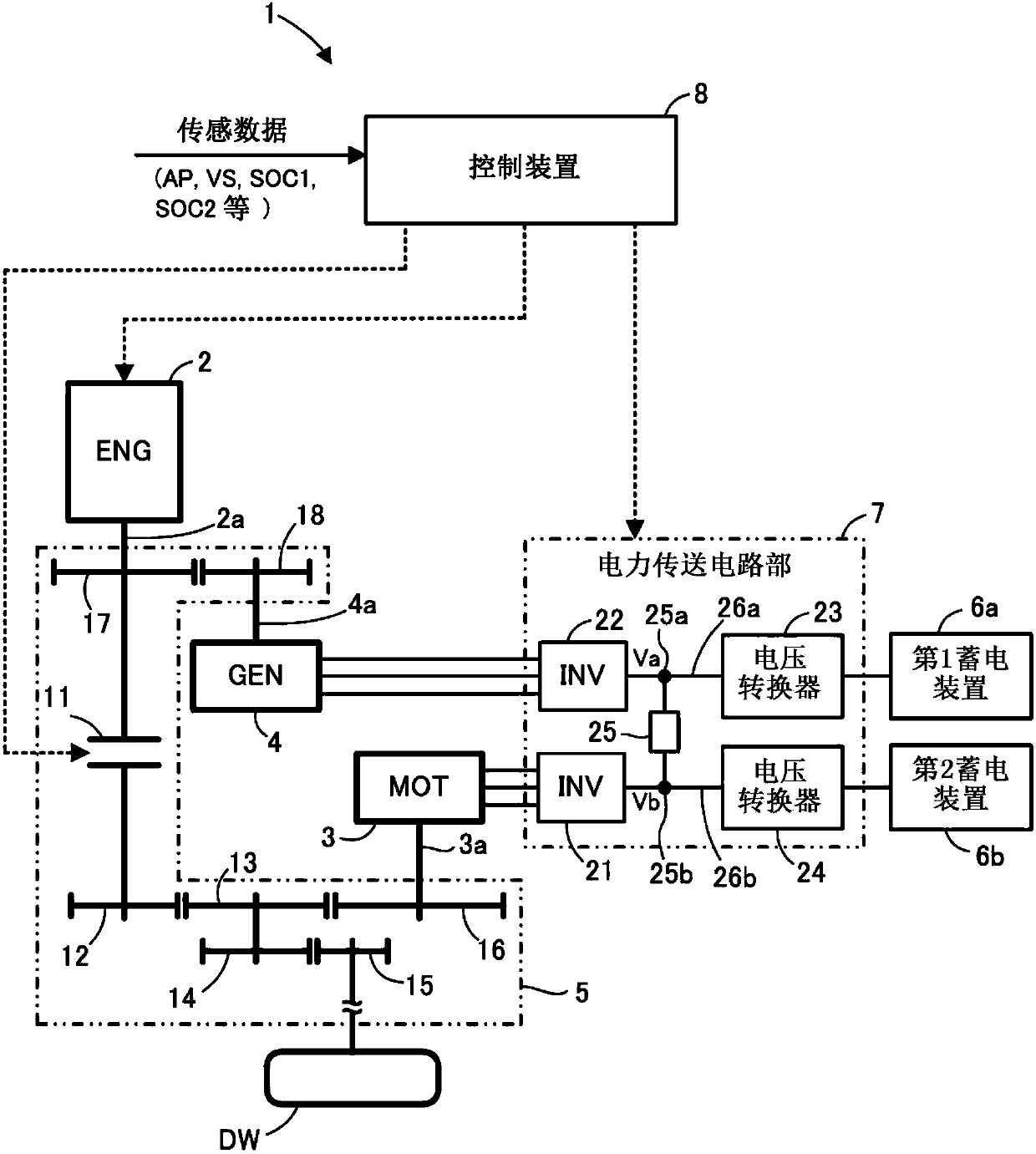
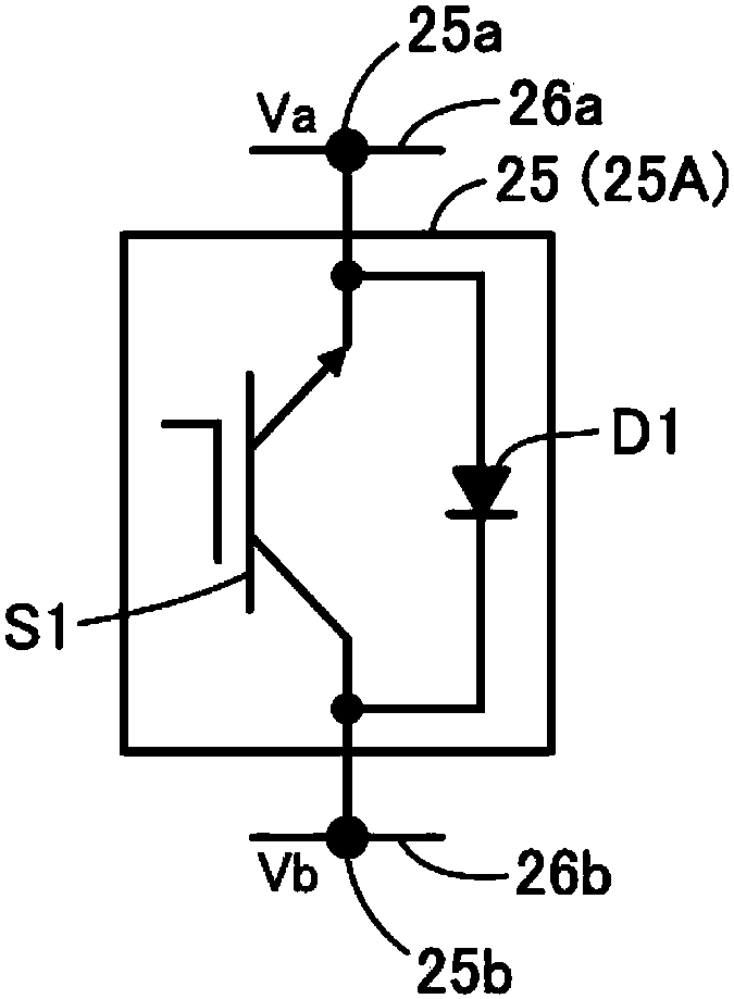
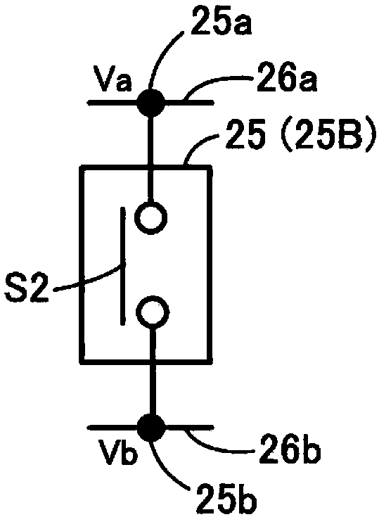
[0067] Below, refer to Figure 1 to Figure 7 One embodiment of the present invention will be described. refer to figure 1 , The power system 1 of the present embodiment is a system mounted on a vehicle (specifically, a hybrid vehicle) as an example of transportation equipment.

[0068] This power system 1 includes: an internal combustion engine 2, an electric motor 3, and a generator 4 capable of generating power for rotationally driving drive wheels DW as passive loads; 3a, 4a connected power transmission mechanism 5; the first power storage device 6a and the second power storage device 6b that store the electric power for power running of the motor 3 and the generator 4; the electric motor 3, the generator 4 and the power storage device 6a , 6b between the power transmission circuit unit 7; and the control device 8 having the function of controlling the operation of the power system 1.

[0069]The internal combustion engine 2 (hereinafter referred to as the engine 2 ) has...


PUM


Abstract

The present invention provides a power system, a conveying device and an operation method of the power system. In the power system comprising internal combustion engine, a motor, a generator and two power storage devices, the electric power of the two power storage devices can be used in an appropriate manner, at the same time, the power of the motor and the generator is transmitted to a driven load. The power system 1 includes: the internal combustion engine 2, the motor 3, the generator 4, a power transmission mechanism 5, a control device 8 and the two power storage devices (6a, 6b). The control device (8) has a function of executing the first control processing which enables the power operation of the motor 3 and the generator 4 and transmits the power both of the motor 3 and the generator 4 to the driven load (DW), and in the first control processing, the electric power both of the first power storage device 6a and the second power storage device 6b is used to supply power to themotor 3 and the generator 4.

Description

technical field [0001] The present invention relates to powertrains used in hybrid vehicles and the like. Background technique [0002] Among hybrid vehicles, conventionally known are hybrid vehicles equipped with a power system including an internal combustion engine, a first motor / generator, and a second motor / generator as shown in Patent Documents 1, 2, and 3, for example. Furthermore, Patent Documents 1 and 2 describe a hybrid vehicle equipped with two power storage devices as power sources for a second motor / generator used as a drive source for traveling. [0003] prior art literature [0004] patent documents [0005] [Patent Document 1] Japanese Patent No. 4179351 [0006] [Patent Document 2] Japanese Patent No. 5772781 [0007] [Patent Document 3] Japanese Patent No. 5842486 [0008] In the power system as described above, it is desired to be able to drive passive loads (drive wheels in hybrid vehicles) with sufficient power without using the power of the intern...

Claims


Application Information

Patent Timeline
IPC IPC(8): B60K6/28B60L11/12B60L50/15B60L50/16
CPCB60L50/15B60K6/28B60L7/14B60L15/20B60L15/2054Y02T10/72B60L58/12B60L2240/12B60L2240/54Y10S903/93B60K6/442Y02T10/62Y02T10/70Y02T10/64Y02T10/7072Y02T90/14B60L58/18B60W20/13B60L15/007B60L2210/10B60L2210/30B60L2210/40B60L2240/42B60L2240/44B60L2240/52B60W10/06B60W10/08B60W10/26B60W2510/0666B60W2510/085B60W2510/244B60W2520/10B60W2710/0677B60W2710/086B60W2710/242B60Y2200/92F02B63/04
Inventor 伊藤嘉启
Owner HONDA MOTOR CO LTD
Learn More