AI technical title is built by Patsnap AI team. It summarizes the technical point description of the patent document.
A cement and equipment technology, applied in the field of automatic cement paving equipment, can solve the problems of reduced service life of roads, uneven water distribution, uneven mixing, etc., and achieve the effects of easy popularization, low manufacturing cost, and convenient operation
Active Publication Date: 2019-11-22
安徽方莱建设工程有限公司
View PDF5 Cites 0 Cited by
Summary
Abstract
Description
Claims
Application Information
AI Technical Summary
This helps you quickly interpret patents by identifying the three key elements:
Problems solved by technology
Method used
Benefits of technology
Problems solved by technology
[0005] The present invention overcomes the need to stir the cement before spreading it on the road. Most of the existing methods are to manually use a shovel to mix the sand and gravel. Manually using a shovel to mix the sand and gravel is not only time-consuming It is laborious, and the stirring is uneven. When mixing sand and gravel, it is necessary to distribute water to the sand and gravel. Manually visually inspecting the water distribution is often uneven, which will greatly reduce the service life of the road. The technology to be solved by the present invention The problem is to provide an automatic cement laying equipment
Method used
Image
Click on the blue label to locate the original text in one second.
Reading with bidirectional positioning of images and text.
Examples
Embodiment 1
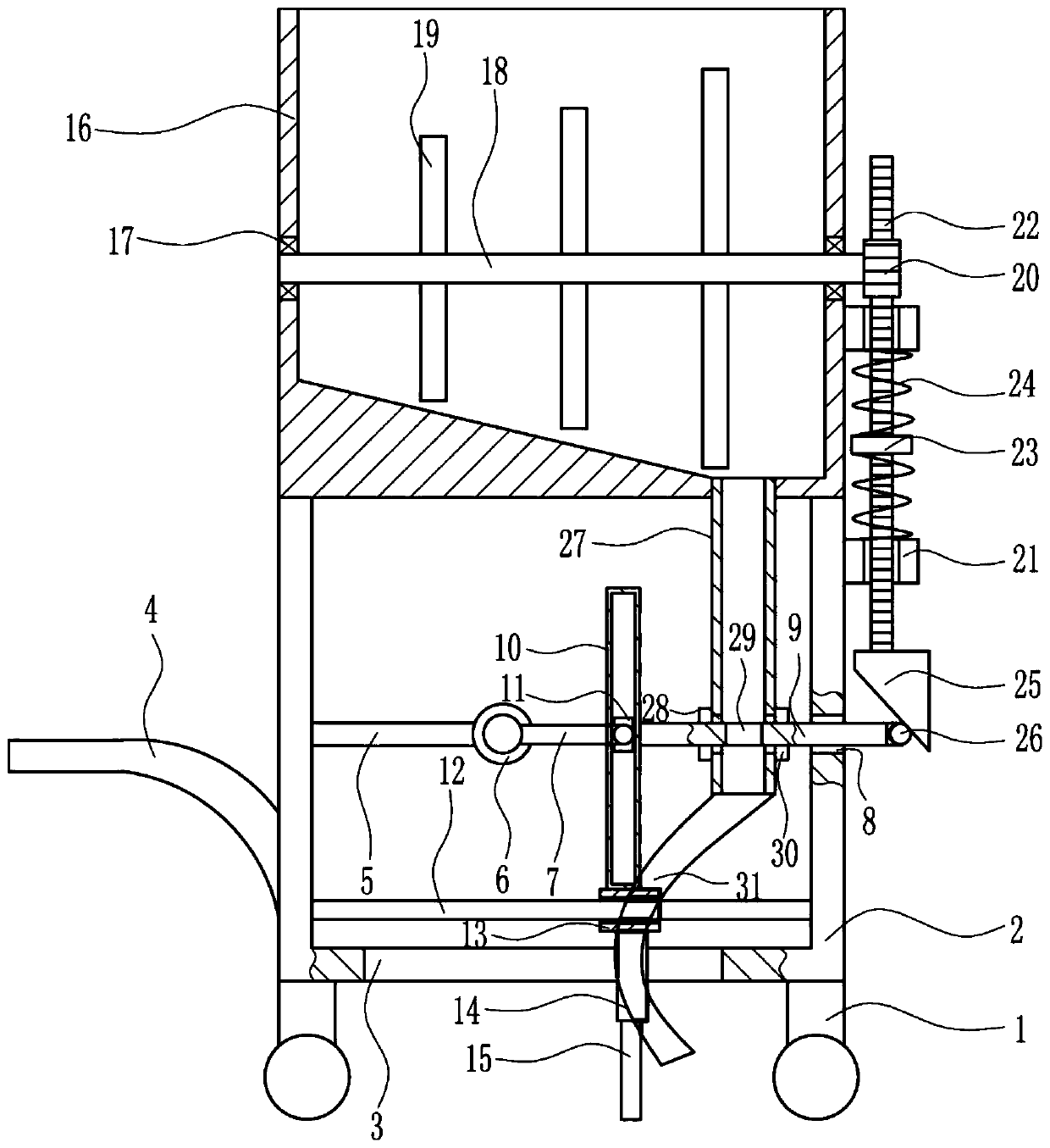
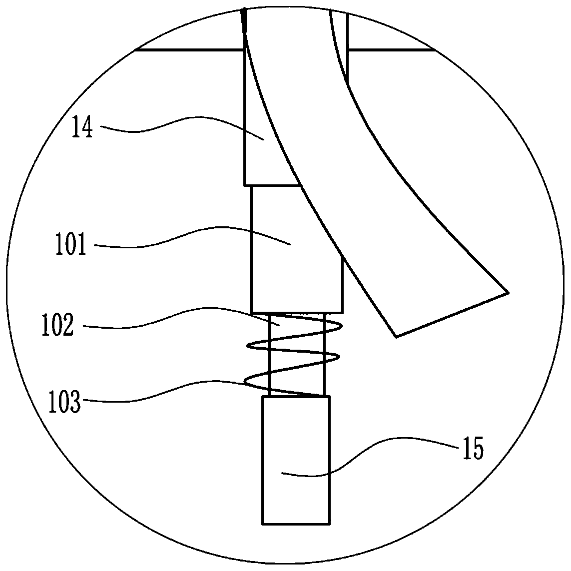
[0018] A kind of automatic cement laying equipment, such as Figure 1-2 As shown, it includes a vehicle frame 1, a frame 2, a handle 4, a bracket 5, a motor 6, a rocker 7, a material retaining plate 9, a straight plate 10, a connecting block 11, a sliding rod 12, a first sliding sleeve 13, and a cylinder 14. Baffle plate 15, stirring box 16, bearing 17, rotating shaft 18, stirring rod 19, gear 20, second sliding sleeve 21, rack 22, block 23, first spring 24, cam 25, roller 26, lower Material pipe 27, fixed block 30 and universal connecting pipe 31 are welded with frame 2 on the top of vehicle frame 1, and are provided with a first through hole 3 below frame 2, and are fixedly connected on the outside of the left wall of frame 2. There is a handle 4, a bracket 5 is fixedly connected to the inner side of the left wall of the frame 2, a motor 6 is arranged on the bracket 5, and a rocking bar 7 is interference-connected on the output shaft of the motor 6, and on the right wall of ...
Embodiment 2
[0020] A kind of automatic cement laying equipment, such as Figure 1-2 As shown, it includes a vehicle frame 1, a frame 2, a handle 4, a bracket 5, a motor 6, a rocker 7, a material retaining plate 9, a straight plate 10, a connecting block 11, a sliding rod 12, a first sliding sleeve 13, and a cylinder 14. Baffle plate 15, stirring box 16, bearing 17, rotating shaft 18, stirring rod 19, gear 20, second sliding sleeve 21, rack 22, block 23, first spring 24, cam 25, roller 26, lower Material pipe 27, fixed block 30 and universal connecting pipe 31 are welded with frame 2 on the top of vehicle frame 1, and are provided with a first through hole 3 below frame 2, and are fixedly connected on the outside of the left wall of frame 2. There is a handle 4, a bracket 5 is fixedly connected to the inner side of the left wall of the frame 2, a motor 6 is arranged on the bracket 5, and a rocking bar 7 is interference-connected on the output shaft of the motor 6, and on the right wall of ...
PUM
Abstract
The invention relates to cement paving equipment, in particular to automatic cement paving equipment. The invention aims to provide the automatic cement paving equipment. In order to achieve the aim,the invention provides the automatic cement paving equipment. The automatic cement paving equipment comprises a vehicle frame, a machine frame, a handle, a bracket, a motor and the like; the machine frame is welded above the vehicle frame; a first through hole is formed below the machine frame; the outer side of the left wall of the machine frame is fixedly connected with the handle; the inner side of the left wall of the machine frame is fixedly connected with the bracket; the motor is arranged on the bracket; an output shaft of the motor is in interference connection with a rocking rod; a first guide hole is formed in the right wall of the machine frame. The automatic cement paving equipment realizes an automatic stirring function, also realizes a function of stirring a large amount of sandstones, achieves the effect of paving the sandstones flatly and also achieves the effect of indirectly feeding; furthermore, the automatic cement paving equipment has the characteristics of high road paving speed, convenience in operation, simplicity in manufacturing, low manufacturing cost, convenience in popularization and the like.
Description
technical field [0001] The invention relates to cement laying equipment, in particular to an automatic cement laying equipment. Background technique [0002] Cementmortar has high strength and good water resistance, and is mostly used in important buildings and water parts of buildings. It is made of cement, sand, and water according to the specified ratio. [0003] When laying cement on the road surface, it is necessary to mix the cement and then spread it on the road surface. Most of the existing methods are to mix the sand and gravel manually with a shovel. Manually using a shovel to mix the sand and gravel is not only time-consuming and laborious, but also Also, the mixing is uneven. When mixing sand and gravel, it is necessary to distribute water to the sand and gravel. Manual visual inspection of water distribution often results in uneven water distribution, which will greatly reduce the service life of the road. Therefore, it is urgent to develop an automatic cement...
Claims
Application Information
Patent Timeline
Application Date:The date an application was filed.
Publication Date:The date a patent or application was officially published.
First Publication Date:The earliest publication date of a patent with the same application number.
Issue Date:Publication date of the patent grant document.
PCT Entry Date:The Entry date of PCT National Phase.
Estimated Expiry Date:The statutory expiry date of a patent right according to the Patent Law, and it is the longest term of protection that the patent right can achieve without the termination of the patent right due to other reasons(Term extension factor has been taken into account ).
Invalid Date:Actual expiry date is based on effective date or publication date of legal transaction data of invalid patent.

