Lever type camshaft-free air valve drive mechanism of piezoelectric driving

A piezoelectric drive and drive mechanism technology, applied to engine components, machines/engines, non-mechanically actuated valves, etc., can solve the problems of increasing the cost of the whole machine, reducing the reliability of the system, and difficult to achieve valve opening, etc.

Pending Publication Date: 2018-04-03
ZHEJIANG NORMAL UNIVERSITY
View PDF0 Cites 2 Cited by
  • Summary
  • Abstract
  • Description
  • Claims
  • Application Information

AI Technical Summary

Problems solved by technology

The camless valve drive mechanism is more flexible in the control of the working parameters of the valve, and the working state of the valve can be varied in a wide range to meet the engine working requirements under various working conditions. However, for the control of the seating speed of the valve, There are still some problems in the precise control of the valve movement trajectory. In addition, most camshaft-free valve drive mechanisms are difficult to realize the partial opening of the valve and maintain this lift. To achieve this goal, more complex and more The precise driving mechanism reduces the reliability of the system and increases the cost of the whole machine

Method used


Image

  • Lever type camshaft-free air valve drive mechanism of piezoelectric driving

Examples


Embodiment Construction

[0017] An embodiment of the present invention will be described in detail with reference to the accompanying drawings.

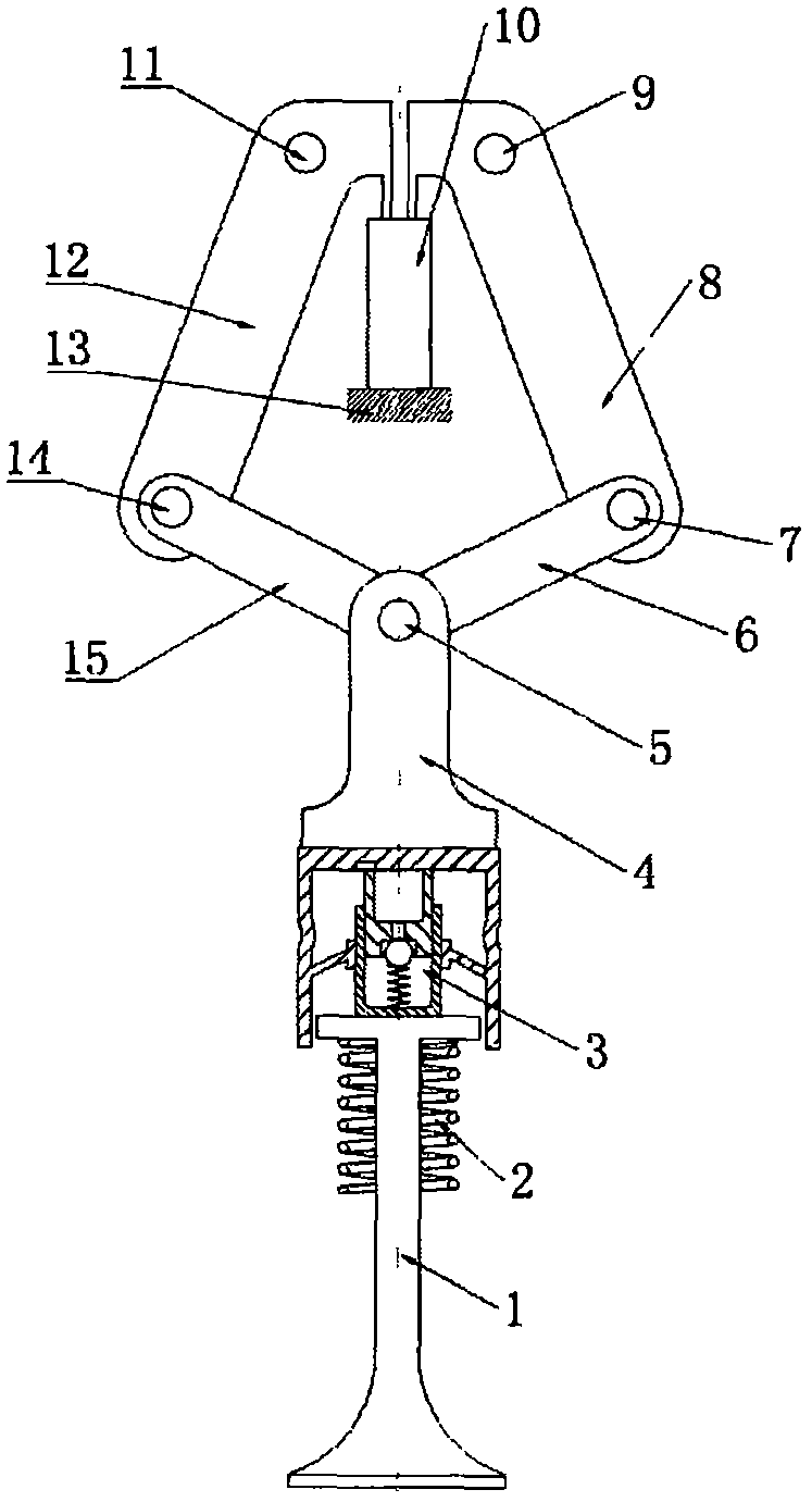
[0018] Such as figure 1 As shown, a piezoelectrically driven lever camshaftless valve drive mechanism includes a piezoelectric driver (10) installed on the cylinder head platform, the centerline of which coincides with the centerline of the valve, symmetrical with respect to the centerline, and fixedly installed on the cylinder The left fulcrum (11) and right fulcrum (9) on the cover, the left swing rod (12) and the right swing rod (8) are respectively installed on the corresponding fulcrums, and the first end of the swing rod is connected to the piezoelectric actuator. The upper end surface of (10) is in close contact, the second end of the left rocker (12) is hinged with the first end of the left rocker (15) through pin B (14), and the second end of the right rocker (8) The end is hinged with the first end of the right rocker (6) through pin A (7), and th...


PUM


Abstract

The invention relates to a lever type camshaft-free air valve drive mechanism of piezoelectric driving. A piezoelectric driver is utilized for generating different deformation elongations along with changes of input voltage. By means of a swinging rod and rocking rod combination mechanism, the stroke is enlarged, and an air valve is driven to be opened. The lever type camshaft-free air valve drivemechanism of piezoelectric driving is high in rigidity, response time is short, air valve lift control is flexible, the seating speed of the air valve can be directly controlled by means of the inputvoltage of the piezoelectric driver, operation parameters of the air valve can be controlled freely within the large range, and the requirements of different working conditions of an engine and various novel combustion technologies are met. The lever type camshaft-free air valve drive mechanism of piezoelectric driving comprises the piezoelectric driver, fixed pivots arranged symmetrically, a swinging rod, a rocking rod, a pushing rod and a hydraulic tappet, wherein the pushing rod and the hydraulic tappet are arranged above an air valve rod.

Description

technical field [0001] The invention relates to an engine gas distribution mechanism, in particular to an engine camshaftless valve driving mechanism, in particular to a piezoelectrically driven lever type camshaftless valve driving mechanism. Background technique [0002] The variable valve mechanism can improve the working performance of the engine at different speeds, but because the variable valve mechanism is based on the traditional camshaft valve mechanism, the range of parameters such as valve timing and opening lift is relatively limited. The camshaftless valve drive mechanism cancels the camshaft in the traditional valve mechanism, and uses other methods to directly drive the valve action. At present, there are mainly several working forms such as electromagnetic drive, electro-hydraulic drive, and electric drive. The camless valve drive mechanism is more flexible in the control of the working parameters of the valve, and the working state of the valve can be varie...

Claims


Application Information

Patent Timeline
IPC IPC(8): F01L9/04F01L13/00F01L1/245F01L9/24
CPCF01L1/245F01L13/0015F01L9/24F01L9/20
Inventor 董颖常占辉
Owner ZHEJIANG NORMAL UNIVERSITY
Why Eureka
Try Eureka