

Optical path debugging device for a fiber-optic gyroscope
A fiber optic gyroscope and optical path technology, applied in measuring devices, instruments, etc., can solve the problems of low automation, low efficiency, inability to meet large batches, and precision requirements in the production environment of fiber optic gyroscopes, and achieve the effect of improving product engineering
- Summary
- Abstract
- Description
- Claims
- Application Information
AI Technical Summary
Problems solved by technology
Method used
Image

Examples
Embodiment Construction
[0021] In order to make the purpose, content, and advantages of the present invention clearer, the specific implementation manners of the present invention will be further described in detail below in conjunction with the accompanying drawings and embodiments.
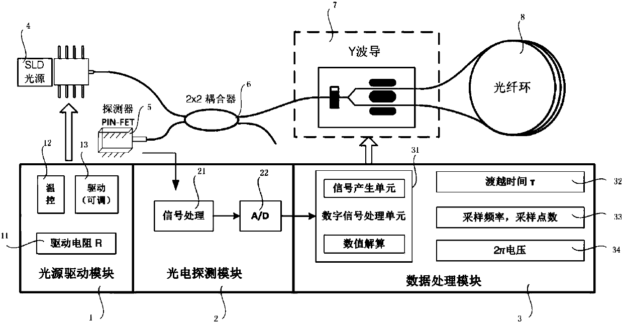
[0022] figure 1 Shown is the block diagram of the optical path debugging equipment used in the present invention for fiber optic gyroscope, as figure 1 As shown, the optical path debugging equipment for the fiber optic gyroscope includes: a light source driving module 1 , a photoelectric detection module 2 and a data processing module 3 . The light source driver module 1 provides the temperature control and drive required by the SLD light source 4. Through the change of the adjustable resistance value, the output power of the light source is changed to provide the required fiber output power for the entire optical path; the photoelectric detection module 2 is a PIN-FET detection The power supply of the detector 5, and...
PUM
 Abstract
Description
Claims
Application Information