Ankle-foot prosthesis device

一种动力型、假肢的技术,应用在假体、医药科学、人造腿等方向,能够解决电池无法假肢供应充足等问题,达到降低力矩和功率要求、降低能耗、缩小电机和电池尺寸的效果

Active Publication Date: 2018-04-06
THE CHINESE UNIVERSITY OF HONG KONG
View PDF11 Cites 10 Cited by
  • Summary
  • Abstract
  • Description
  • Claims
  • Application Information

AI Technical Summary

Problems solved by technology

However, due to the limitation of battery energy density, it is difficult for most commercial batteries to provide the power consumption required by the prosthesis for a day while meeting the size and weight requirements of the ankle-foot prosthesis.
[0004] In addition, when the wearer walks for a long time, the battery cannot supply sufficient energy for the prosthesis

Method used


Image

  • Ankle-foot prosthesis device
  • Ankle-foot prosthesis device
  • Ankle-foot prosthesis device

Examples


Embodiment Construction

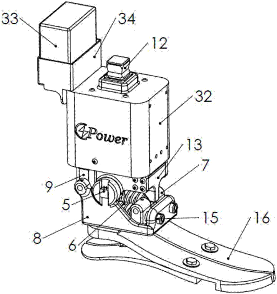
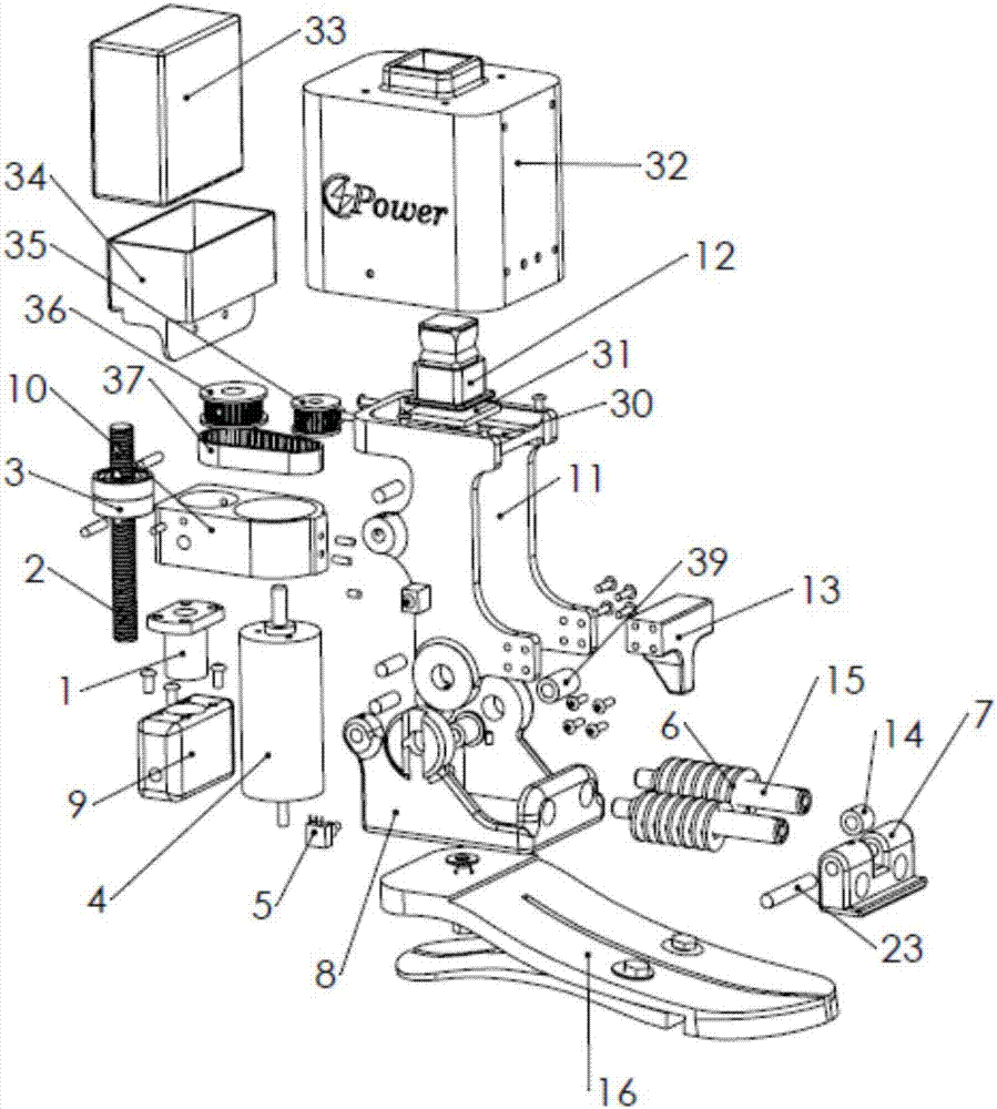
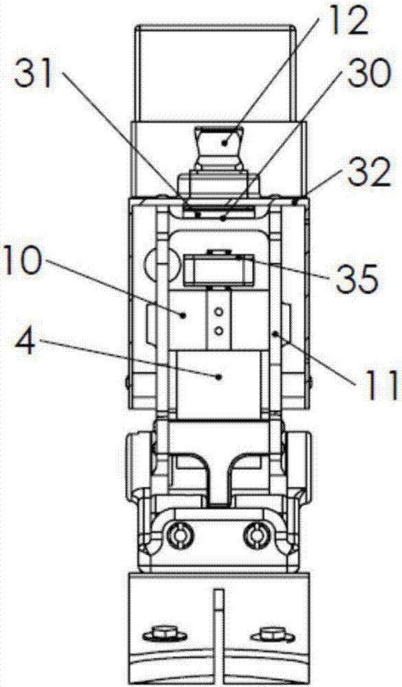
[0022] Embodiments of the present invention relate to powered ankle-foot prostheses employing elastic components and actuators. The invention is described in detail with reference to the drawings; like reference numerals are used to designate like elements.

[0023] Figure 1 to Figure 4 It is a specific embodiment of the ankle-foot prosthesis proposed by the present invention. The elastic foot 16 is used to reduce the impact force during the heel strike. The elastic feet 16 may be implemented as carbon fiber feet, or any suitable material with sufficient strength and elasticity. As described herein, elastic feet refer to any type of shock absorbing foot that may utilize various features or mechanisms (eg, elastomers, spring mechanisms, elastic blades, pistons, etc.). The ankle-foot prosthesis includes a foot mount 20 for attaching the elastic foot 16 . Foot mount 20 may include a flat surface with threaded holes. The fastening bolt 21 connects the shock-absorbing foot 16...


PUM


Abstract

A powered ankle-foot prosthesis and associated methods of use are described herein. Such prostheses can employ an actuator and elastic components, the actuator being controlled to deliver net positivework to propel the wearing amputee forward and the elastic components being used to store and release negative energy to improve efficiency. Elastic components can be linear springs coupled with a cam and configured in parallel to the actuator. The cam profile can be designed to generate a desired spring torque versus angle curve rather than a spring stroke versus angle curve, thereby reproducinghuman ankle controlled dorsiflexion stiffness. Such configurations improve system energy efficiency and reduce both actuator torque and power requirements. Such prostheses can also operate in a passive mode, in which a nearly normal gait can be achieved even without powered assist.

Description

Background technique [0001] This application claims the benefit of priority to US Non-Provisional Application No. 15 / 280,788, filed September 29, 2016, the entire contents of which are hereby incorporated by reference in their entirety for all purposes. [0002] Ankle-foot prostheses, also known as tibial prostheses, are used to help restore walking function in individuals with below-the-knee amputations. Existing commercial tibial prostheses can generally be divided into two main types: passive tibial prostheses and powered tibial prostheses. Passive tibial prostheses do not include actuators and therefore do not provide the net positive work during the gait cycle as normal human ankles do. The lack of positive work input will prevent the amputee from regaining a more natural walking gait. For some passive prostheses, a spring-clutch mechanism can be used to adjust the ankle angle during walking or reduce the wearer's walking power consumption. However, clinical studies ha...

Claims


Application Information

Patent Timeline
Patent Type & Authority Applications(China)
IPC IPC(8): A61F2/60A61F2/66A61F2/68A61F2/70
CPCA61F2/60A61F2/66A61F2/6607A61F2002/6657A61F2002/607A61F2002/6614A61F2002/701A61F2002/5009A61F2002/5075A61F2002/7625A61F2002/7635A61F2002/7645A61F2002/6664A61F2002/704A61F2/70
Inventor 高飞刘炎南廖维新
Owner THE CHINESE UNIVERSITY OF HONG KONG
Why Eureka
Try Eureka