
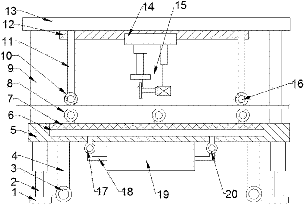
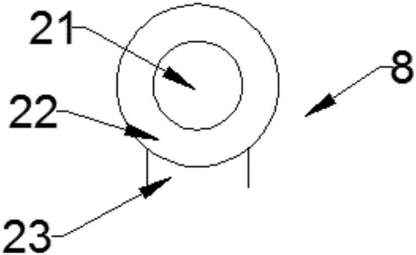
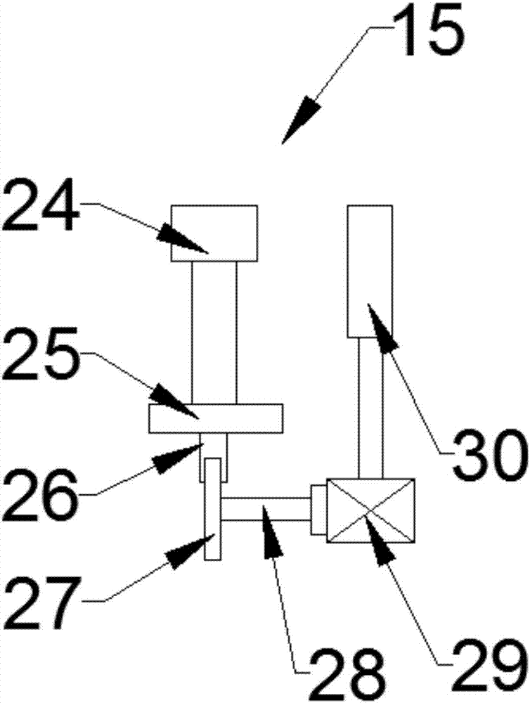
Convenient architectural decoration plate cutting device

A cutting device and architectural decoration technology, applied in metal processing and other directions, can solve the problems of complex structure, inconvenient cutting, inconvenient feeding, etc., and achieve the effects of good cutting effect, simple structure and strong practicability

Inactive Publication Date: 2018-04-06
ZHENGZHOU LIFUAI BIOLOGICAL TECH CO LTD
View PDF4 Cites 12 Cited by
  • Summary
  • Abstract
  • Description
  • Claims
  • Application Information

AI Technical Summary

Problems solved by technology

[0002] Building decorative board is a kind of man-made building decorative board. It is a thermosetting laminated plastic made of high-temperature and high-pressure adhesive after chemical treatment of various special papers. It is bright and beautiful, and has good physical properties such as high wear resistance, heat resistance, cold resistance, and fire prevention; the walls and roofs of many high-end houses, exquisitely made cabinets, cupboards, tables, beds, workbenches for precision instruments, laboratory Most of the shells of laboratory benches, televisions, radios and other broadcasting and telecommunications equipment use decorative panels; when building decorative panels are in use, they need to be cut according to the use area. Complicated, with disadvantages of inconvenient feeding and inconvenient cutting; therefore, improvement is required

Method used


Image

  • Convenient architectural decoration plate cutting device
  • Convenient architectural decoration plate cutting device
  • Convenient architectural decoration plate cutting device

Examples


Embodiment Construction

[0016] The technical solution of this patent will be further described in detail below in conjunction with specific embodiments.

[0017] Embodiments of the present patent are described in detail below, examples of which are shown in the drawings, wherein the same or similar reference numerals designate the same or similar elements or elements having the same or similar functions throughout. The embodiments described below by referring to the figures are exemplary and are only used for explaining the patent, and should not be construed as limiting the patent.

[0018] In the description of this patent, it is to be understood that the terms "center", "upper", "lower", "front", "rear", "left", "right", "vertical", "horizontal", The orientation or positional relationship indicated by "top", "bottom", "inner", "outer", etc. is based on the orientation or positional relationship shown in the drawings, and is only for the convenience of describing this patent and simplifying the des...


PUM


Abstract

The invention provides a convenient architectural decoration plate cutting device, and belongs to the technical field of architecture cutting. The convenient architectural decoration plate cutting device comprises a supporting device and a cutting device; a sliding block is slidingly arranged on a sliding rail; a placing mesh plate is arranged at the upper end of a waste chipping collection cavity; the upper end of a first suction fan is connected with the left side of the lower surface of the waste chipping collection cavity through a dust pipe; the right end of a waste chipping collection box is connected with a second suction fan through a dust pipe; and the upper end of the second suction fan is connected with the right side of the lower surface of the waste chipping collection cavitythrough a dust pipe. The cutting device is arranged at the lower end of the sliding block, so that the convenient architectural decoration plate cutting device has a function of cutting architecturaldecoration plates; transmission devices are arranged on the upper surface of the placing mesh plate, so that the convenient architectural decoration plate cutting device has a function of conveying the decoration plates; the left end of the waste chipping collection box is connected with the first suction fan through the dust pipe, so that the convenient architectural decoration plate cutting device has a function of collecting waste chippings generated in the cutting process; and the convenient architectural decoration plate cutting device has the characteristics of simple structure, high practicability and good cutting effect.

Description

technical field [0001] The invention relates to a building-related facility, in particular to a portable cutting device for building decorative boards. Background technique [0002] Building decorative board is a kind of man-made building decorative board. It is a thermosetting laminated plastic made of high-temperature and high-pressure adhesive after chemical treatment of various special papers. It is bright and beautiful, and has good physical properties such as high wear resistance, heat resistance, cold resistance, and fire prevention; the walls and roofs of many high-end houses, exquisitely made cabinets, cupboards, tables, beds, workbenches for precision instruments, laboratory Most of the shells of laboratory benches, televisions, radios and other broadcasting and telecommunications equipment use decorative panels; when building decorative panels are in use, they need to be cut according to the use area. It is complicated, and has the disadvantages of inconvenient f...

Claims


Application Information

Patent Timeline
Patent Type & Authority Applications(China)
IPC IPC(8): B26D1/15B26D5/04B26D7/01B26D7/02B26D7/18B26D7/22B26D7/06B26D7/00
CPCB26D1/15B26D5/04B26D7/00B26D7/01B26D7/025B26D7/06B26D7/1863B26D7/22B26D2007/0012B26D2007/0018
Inventor 张健健
Owner ZHENGZHOU LIFUAI BIOLOGICAL TECH CO LTD
Learn More