Packaging box bracket self-adaptive trundle overturning mechanism

A technology of turning over mechanism and packing box, applied in the direction of external accessories, etc., to achieve the effect of low cost, strong generalization and simple operation

Active Publication Date: 2018-04-06
BEIJING INST OF SPECIALIZED MACHINERY
5 Cites 3 Cited by

AI-Extracted Technical Summary

Problems solved by technology

[0005] The technical problem to be solved by the present invention is: how to design a packing case bracket self-adaptive cast...

Abstract

The invention relates to a packaging box bracket self-adaptive trundle overturning mechanism and relates to the technical field of packaging. According to the packaging box bracket self-adaptive trundle overturning mechanism provided by the invention, the up-down adjustment function is achieved while trundles can be overturned, a packaging box bracket can be supported and locked in any ground environment through a bracket, thus, loading and unloading operation of equipment in packaging boxes can be conducted in any complex ground environment, and the flexibility is improved. The overturning mechanism is small in size, the overall size of the packaging boxes is not increased, operation is simple and can be conducted by hands without any tool, and the overturning mechanism is simple in structure, high in universality, low in cost and high in practicability and can be widely used.

Application Domain

External fittings

Technology Topic

Self adaptiveEngineering +1

Image

  • Packaging box bracket self-adaptive trundle overturning mechanism
  • Packaging box bracket self-adaptive trundle overturning mechanism
  • Packaging box bracket self-adaptive trundle overturning mechanism

Examples

  • Experimental program(1)

Example Embodiment

[0016] In order to make the purpose, content, and advantages of the present invention clearer, the specific embodiments of the present invention will be described in further detail below in conjunction with the accompanying drawings and embodiments.
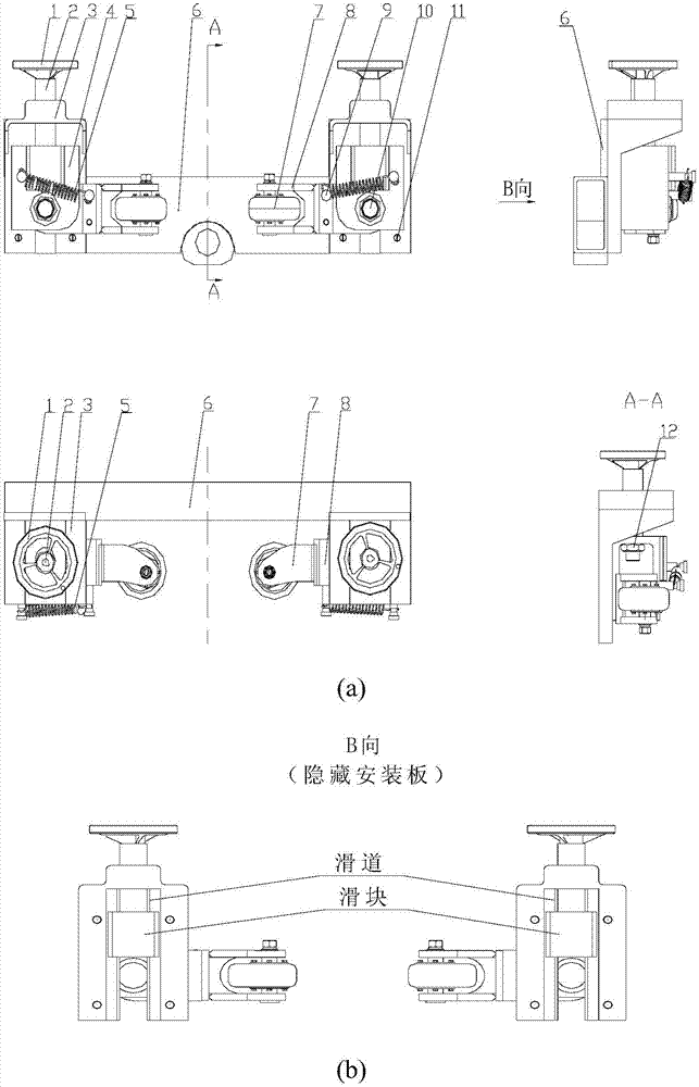
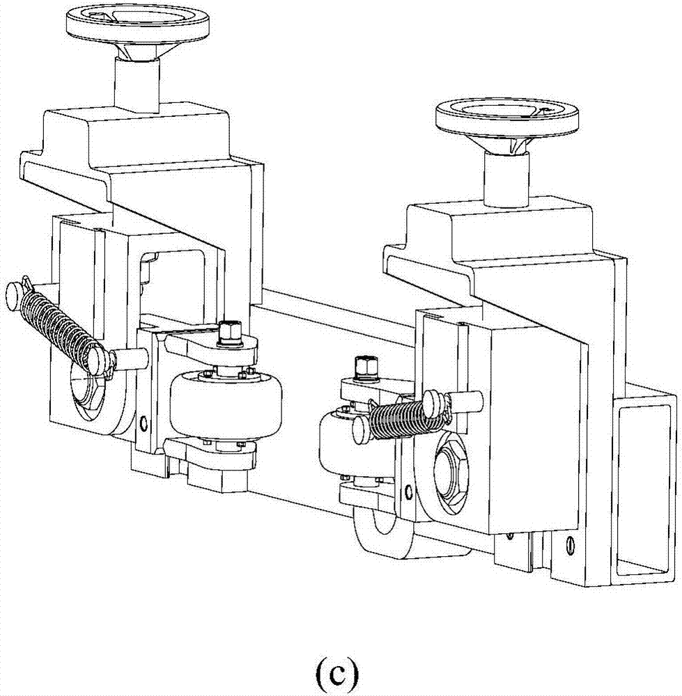
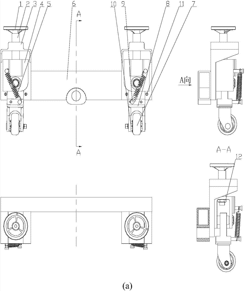
[0017] Such as Figure 1-Figure 2 As shown, the adaptive caster turning mechanism consists of operating hand wheel 1, adjusting rod 2, mechanism mounting seat 3, rotating shaft mounting seat 4, tension spring 5, caster 7, caster mounting seat 8, spring fixing screw 9, rotating shaft 10, screw 11 and a lock nut 12, the entire turning mechanism is fixed on the front end of the bracket 6 by screws 11; the caster 7 and the caster mounting seat 8 are welded into one body, and are connected together by the rotating shaft 10, the rotating shaft mounting seat 4 and the adjusting rod 2 pass The nuts 12 are fixed together, and the operating hand wheel 1 and the adjusting rod 2 are connected together by keys.
[0018] The adjusting rod 2 has a thread, and the matching mechanism mounting seat 3 is provided with threaded holes; the mechanism mounting seat 3 is provided with a slideway (such as figure 1 As shown in (b)), the rotating shaft mounting seat 4 matched with it is provided with a protruding slider; the tension spring 5 is fixed on the rotating shaft mounting seat 4 by a spring fixing screw 9.
[0019] When assembling the mechanism, first fix the mechanism mounting base 3 to the front end of the bracket 6 with screws 11, and at the same time follow figure 1 Assemble the shaft mounting seat 4, the tension spring 5, the casters 7, the caster mounting seat 8, the spring fixing screw 9 and the shaft 10 together, and then move the shaft mounting seat 4 upward along the lowest end of the mechanism mounting seat 3; rotation operation With the hand wheel 1, the adjusting rod 2 passes through the holes in the mechanism mounting seat 3 and the shaft mounting seat 4, and the lock nut 12 is used to lock it.
[0020] During storage and transportation, the turning mechanism is stowed horizontally, and the caster 7 is in a horizontal state under the action of the spring force of the tension spring 5, such as figure 1 Shown.
[0021] When using, first turn the caster 7 down 90° along the shaft 10 to make it in a vertical state (such as figure 2 As shown), then rotate the handwheel 1 left and right, and drive the raised slider on the shaft mounting seat 4 through the adjustment lever 2 to slide up and down along the slideway provided on the mechanism mounting seat 3 (the raised slide block on the shaft mounting seat 4 Cooperate along the slideway on the mechanism mounting seat 3, and at the same time limit the degree of freedom of the caster shaft mounting seat 3, the caster 7 and the caster mounting seat 8 in other directions), make the caster 7 touch the ground, and then carry out the equipment loading and unloading operations. After the operation is completed, push the bracket 6 into the packing box. After the bracket 6 is in place, turn the caster 7 upward along the rotating shaft 10 by 90° to make it in a horizontal state.
[0022] The above are only the preferred embodiments of the present invention. It should be pointed out that for those of ordinary skill in the art, without departing from the technical principles of the present invention, several improvements and modifications can be made. These improvements and modifications It should also be regarded as the protection scope of the present invention.

PUM

no PUM

Description & Claims & Application Information

We can also present the details of the Description, Claims and Application information to help users get a comprehensive understanding of the technical details of the patent, such as background art, summary of invention, brief description of drawings, description of embodiments, and other original content. On the other hand, users can also determine the specific scope of protection of the technology through the list of claims; as well as understand the changes in the life cycle of the technology with the presentation of the patent timeline. Login to view more.

Similar technology patents

Method for manufacturing flexible backplane, liquid crystal display panel and OLED display panel

ActiveCN107359177AImprove flexibility
Owner:WUHAN CHINA STAR OPTOELECTRONICS SEMICON DISPLAY TECH CO LTD

Method for preparing silicon oil

InactiveCN102898654AImprove flexibilityExcellent slip and rebound
Owner:FUYANG HESHI CHEM FIBER AUX CO LTD

Onsite steel rail laser processing vehicle

ActiveUS20150020707A1save timeimprove flexibility
Owner:WUHAN HIVALUE INTELASER LTD

Classification and recommendation of technical efficacy words

  • small size
  • Improve flexibility

Microfabricated elastomeric valve and pump systems

InactiveUS6929030B2high speedsmall size
Owner:CALIFORNIA INST OF TECH

RFID antenna

InactiveUS20060208900A1high efficiencysmall size
Owner:TRANSPACIFIC TECH

Capacitor module, power converter, vehicle-mounted electrical-mechanical system

ActiveUS20070109715A1reduce surge voltagesmall size
Owner:HITACHI ASTEMO LTD

Projection display chip

InactiveUS20100321640A1small sizehigh efficiency
Owner:IND TECH RES INST

Phase-change energy-storage material nanocapsule and preparation method thereof

ActiveCN104449590Asmall sizeImprove stability
Owner:INST OF CHEM MATERIAL CHINA ACADEMY OF ENG PHYSICS
Why Eureka
Try Eureka