

Wet dust removal system for sweeping vehicle
A technology of wet dust removal and cleaning vehicles, applied in cleaning methods, road surface cleaning, construction, etc., can solve the problems of secondary dust pollution, large space, energy consumption, etc., and achieve simple and compact structure, energy saving, and isolation and settlement Effect
- Summary
- Abstract
- Description
- Claims
- Application Information
AI Technical Summary
Problems solved by technology
Method used
Image

Examples
Embodiment Construction
[0032] The present invention will be described in further detail below in conjunction with the accompanying drawings.
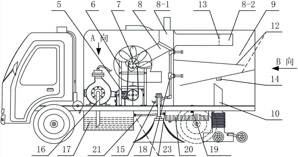
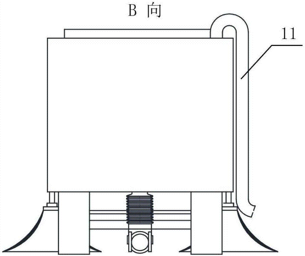
[0033] see Figure 1 to Figure 7 , the present invention includes a power system, an air circulation system and a spraying system installed on the sweeper; a dustbin 9 is installed on the sweeper, and a suction pipe 10 is arranged at the bottom of the dustbin 9 .
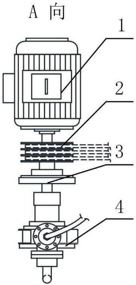
[0034] The power system adopts a motor 1, and the motor 1 is connected to a reducer 5 through a pulley 2, and the reducer 5 is connected to a fan 7. The motor 1 is connected to the water pump 4 by connecting the electromagnetic clutch 3 . A dust concentration detector 14 is installed at the outlet of the suction pipe 10, and the dust concentration detector 14 is connected with the control system, and the control system is connected with the electromagnetic clutch 3.
[0035] see figure 2 , the motor 1, the pulley 2, the electromagnetic clutch 3 and the water pump 4 are arranged coaxially.
[0...
PUM
 Abstract
Description
Claims
Application Information