Adjustable plug-in type flexible grouting device

A plug-in, grouting technology, applied in the field of adjustable plug-in flexible grouting, can solve problems such as affecting grouting efficiency and slowing down the progress of work, and achieve the effect of improving work efficiency and speeding up the progress of work

Inactive Publication Date: 2018-04-06
SOUTHWEST JIAOTONG UNIV
View PDF1 Cites 2 Cited by
  • Summary
  • Abstract
  • Description
  • Claims
  • Application Information

AI Technical Summary

Problems solved by technology

[0005] Aiming at the deficiencies of the existing technology, the purpose of the present invention is to provide an adjustable plug-in flexible grouting device to solve the problem that people in the prior art cannot accurately know how much material is left in the material cup, and it can only be used after use. I learned that it affects people's grouting efficiency and slows down the progress of work

Method used


Image

  • Adjustable plug-in type flexible grouting device
  • Adjustable plug-in type flexible grouting device
  • Adjustable plug-in type flexible grouting device

Examples


Embodiment 1

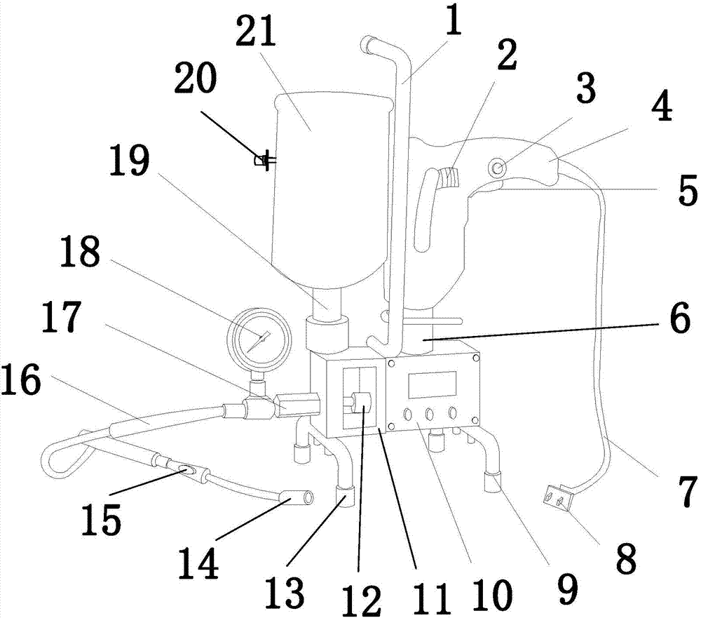
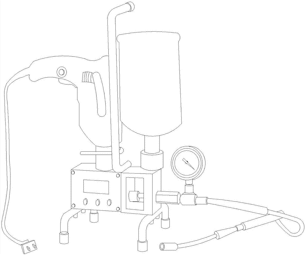
[0031] see Figure 1-Figure 8 , the present invention provides a technical solution of an adjustable plug-in flexible grouter: an adjustable plug-in flexible grouter, the structure of which includes a handle 1, an electric drill cooling hole 2, a fixed lock button 3, and a driving electric drill 4 , trigger 5, fixed column 6, connecting wire 7, power plug 8, right support foot 9, gearbox 10, stainless steel outer protective frame 11, piston 12, left support foot 13, grouting head 14, tank filling switch button 15. High pressure pipe 16, booster cylinder 17, pressure gauge 18, transmission pipe 19, liquid level sensor 20, material cup 21:

[0032] The handle 1 is a U-shaped structure, the lower end of the handle 1 is welded between the gearbox 10 and the upper surface of the stainless steel outer protective frame 11, and the fixing column 6 is installed on the right side of the handle 1 and welded vertically Above the gearbox 10, the driving electric drill 4 is vertically fixe...

Embodiment 2

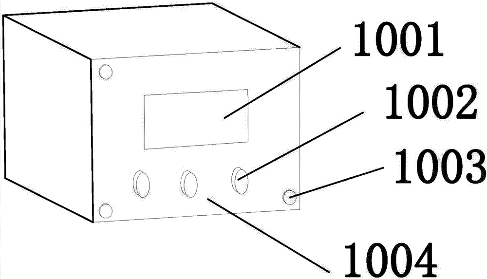
[0039] see Figure 1-Figure 8 , the booster barrel 17 is provided with an oil cylinder 1701, a booster copper guide sleeve 1702, a flange steel plate 1703, a front rod 1704, and a double-layer sealing head 1705, and the booster barrel 17 is an improved design combining the advantages of the cylinder and the oil cylinder , the hydraulic oil is strictly isolated from the compressed air, the piston rod in the cylinder starts automatically after touching the work piece, the action speed is fast, and it is more stable than the pneumatic transmission, the cylinder body device is simple, and the output is easy to adjust. The flange steel plate 1703 is equipped with two , the oil cylinder 1701 is horizontally fixed on the left side of the flange steel plate 1703 on the right side, the pressurized copper guide sleeve 1702 is embedded in the flange steel plate 1703, the front rod 1704 vertically penetrates the flange steel plate 1703 and is connected with the increased The copper pressi...


PUM

PropertyMeasurementUnit
diameteraaaaaaaaaa
diameteraaaaaaaaaa
lengthaaaaaaaaaa

Abstract

The invention discloses an adjustable plug-in type flexible grouting device. The device structurally comprises a handle, an electric drill heat dissipation hole, a fixing lock button, a driving electric drill, a trigger, a fixing column, a connecting wire, a power plug, a right support leg, a gearbox, a stainless steel outer protection frame, a piston, a left support leg, a grouting head, a tank injection switch button, a high pressure pipe, a booster cylinder, a pressure gauge, a conveying pipe, a liquid level sensor, a material cup, a liquid level sensor detection head, a waterproof conveying pipe, a fixing flange plate, a warning lamp and an electric appliance box. According to the adjustable plug-in type flexible grouting device, due to the fact that the liquid level sensor is arranged, when material blocks in the material cup is almost used up, alarm can be send out, so that people can know that the materials are about to be used up, and the materials can be added in time; and shutdown caused by lacking of material can not occur in the emergency grouting process, the working efficiency is improved, and the working progress is accelerated.

Description

technical field [0001] The invention is an adjustable plug-in flexible grouting device, which belongs to the field of grouting devices. Background technique [0002] To insert means to put in, squeeze in, pierce, penetrate; add into. [0003] Grouting is divided into ceramic craft grouting and construction engineering grouting. Ceramic technology grouting is a process of injecting prepared mud into ceramic production. Construction engineering is a method of injecting some curable grout into the cracks or pores of rock foundations with appropriate methods, and improving its physical and mechanical properties by means of replacement, filling, extrusion, etc. [0004] The prior art discloses a grouting device with the application number: 201620946173.7, which includes: a pipe body with a plugging end and an input end, the plugging end is equipped with a plugging cover, and the input end is used for continuous grouting A tube, the tube body is provided with an output hole; an...

Claims


Application Information

Patent Timeline
Patent Type & Authority Applications(China)
IPC IPC(8): E02D3/12E02D15/02B28B1/26
CPCE02D3/12B28B1/26E02D15/02E02D2250/003
Inventor 杨长卫孙泽仁令狐勇生童心豪曲宏略张建经
Owner SOUTHWEST JIAOTONG UNIV
Why Eureka
Try Eureka