
Test system for DSP (digital signal processing) unit in field programmable gate array chip

A test system and gate array technology, applied in the direction of test/monitoring control system, general control system, electrical test/monitoring, etc., can solve the problems of normal DSP unit function, abnormal function of test result display, poor accuracy, etc., and achieve accurate function The effect of the test

Inactive Publication Date: 2018-04-06
SHANGHAI FUDAN MICROELECTRONICS GROUP
View PDF12 Cites 2 Cited by
  • Summary
  • Abstract
  • Description
  • Claims
  • Application Information

AI Technical Summary

Problems solved by technology

[0005] However, the above-mentioned test method usually tests the function of the DSP unit when the DSP clock frequency is low. When the function of the DSP unit is tested under the condition of a high DSP clock frequency, the DSP unit may function normally, but the test results show that the function Unusual situation, less accurate

Method used


Image

  • Test system for DSP (digital signal processing) unit in field programmable gate array chip
  • Test system for DSP (digital signal processing) unit in field programmable gate array chip
  • Test system for DSP (digital signal processing) unit in field programmable gate array chip

Examples


Embodiment Construction

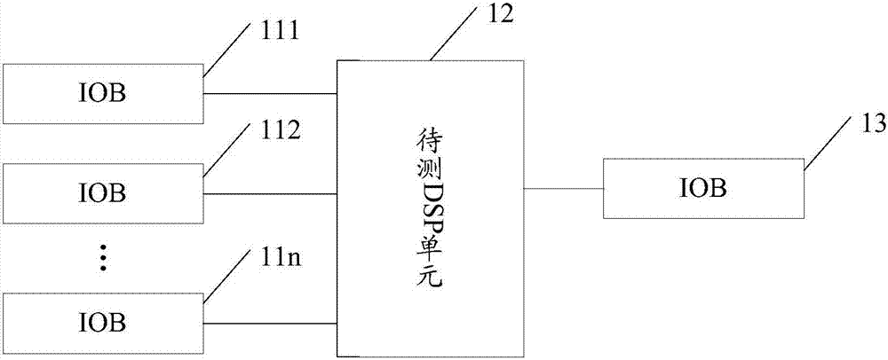
[0023] figure 1 It is a schematic diagram of a testing system of a DSP unit in an existing FPGA chip. Such as figure 1 As shown, the input and output units (IOBs) 111-11n in the FPGA chip are connected to the DSP unit 12 to be tested through interconnection resources in the FPGA chip. The excitation data are respectively input to the DSP unit 12 to be tested by the IOB111-11n, and the DSP unit 12 to be tested performs corresponding operations on the excitation data, and then outputs the operation result data through the IOB13. The user can judge whether the function of the DSP unit 12 under test is normal by comparing the output calculation result data with the expected data, that is, whether the DSP unit 12 under test is working normally.

[0024] In the above test system, multiple IOBs need to be used, and each IOB is connected to the DSP unit 12 to be tested through different interconnection resources. Due to the different delays of different interconnection resources, d...


PUM


Abstract

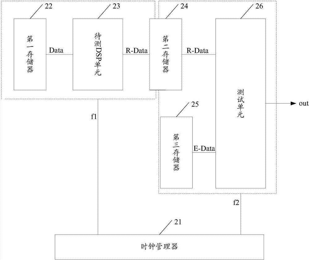
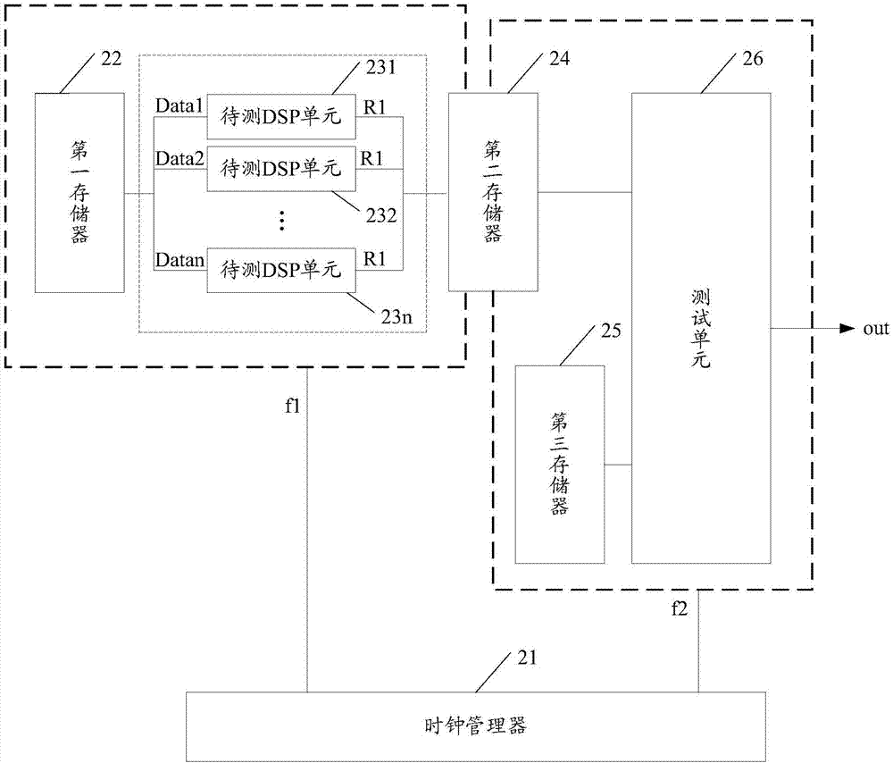
The invention relates to a test system for a DSP (digital signal processing) unit in a field programmable gate array chip. The system includes a clock manager, a first memory, a DSP unit to be tested,a second memory, a third memory, and a test unit; a clock frequency at which data are written into the second memory is the same as the operating frequency of the first memory and the DSP unit to betested; a clock frequency at which data are read from the second memory is the same as the operating frequency of the third memory and the test unit; the clock manager is suitable for providing a first clock frequency and a second clock frequency, wherein the first clock frequency is greater than the second clock frequency; and the DSP unit to be tested is suitable for acquiring excitation data from the first memory at the first clock frequency, performing predetermined arithmetic operation on the excitation data and outputting operation result data to the second memory. With the above systemadopted, the accuracy of the test of the function of the DSP unit under a high frequency can be improved.

Description

technical field [0001] The invention relates to the technical field of testing, in particular to a testing system for a DSP unit in a field programmable gate array chip. Background technique [0002] Field Programmable Gate Array (Field-Programmable Gate Array, FPGA) is further developed on the basis of programmable devices such as Programmable Logic Array (Programmable Logic Array, PAL) and General Logic Array (Generic Logic Array, GAL). of. As a semi-custom circuit in the field of application-specific integrated circuits (ASIC), FPGA not only solves the shortcomings of custom circuits, but also overcomes the shortcomings of the limited number of original programmable device gate circuits. [0003] In recent years, FPGA chips have been widely used in various fields. With the increase of the size and complexity of the FPGA chip, in the design stage, the function verification of each logic unit becomes the key to FPGA chip design. [0004] As a basic logic unit in the FPGA...

Claims


Application Information

Patent Timeline
Patent Type & Authority Applications(China)
IPC IPC(8): G05B23/02
CPCG05B23/0256
Inventor 陈宁俞军沈磊俞剑张智丰震昊周慧
Owner SHANGHAI FUDAN MICROELECTRONICS GROUP
Learn More