
Function test system for TCON board and TCONLESS mainboard

A functional testing and motherboard technology, applied in the direction of electronic circuit testing, measuring electricity, measuring devices, etc., can solve the problems of unstable test results, inconvenient use, poor compatibility, etc., and achieve the effect of efficient functional testing

Pending Publication Date: 2021-03-12
广州晶序达电子科技有限公司
View PDF5 Cites 2 Cited by
  • Summary
  • Abstract
  • Description
  • Claims
  • Application Information

AI Technical Summary

Problems solved by technology

The device mainly has the following three problems: 1. Since the device connects the test signal with the test point on the TCON board through the fixture test PIN, the device cannot accurately detect the problem caused by the soldering of the TCON board connector.
2. The PCI DAQ and PCI miniLVDS acquisition cards of this device are installed in the host computer. The connection between the fixture test PIN and the acquisition card is long. stability problem
3. The device needs to be replaced with different types of acquisition cards for TCON boards with different interface protocols, which is inconvenient to use and has poor compatibility
However, this module cannot detect the high-speed differential signal output by the TCON board, so the test result is not accurate enough

Method used


Image

  • Function test system for TCON board and TCONLESS mainboard
  • Function test system for TCON board and TCONLESS mainboard
  • Function test system for TCON board and TCONLESS mainboard

Examples


Embodiment 1

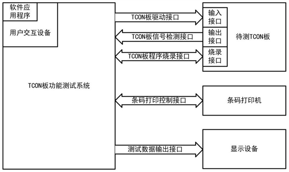
[0054] Such as figure 2 As shown, the drive interface of the TCON board of this system is connected with the input interface of the TCON board to be tested, the output interface of the TCON board to be tested is connected with the signal detection interface of the TCON board of the system, and the programming interface of the TCON board of the system is connected with the The programming interface of the TCON board to be tested is connected, the barcode printing control interface of the system is connected with the barcode printer, the test data output interface of the system is connected with the display device, and the display device refers to a computer monitor or an LCD screen.

Embodiment approach 1

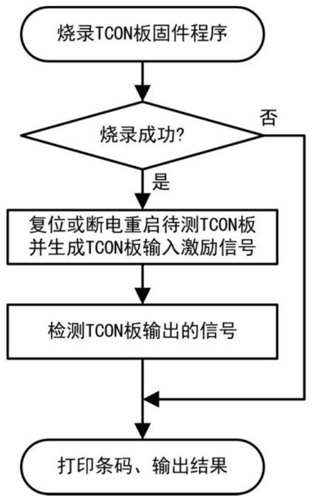
[0055] The flow chart of Embodiment 1 is as follows image 3 As shown, the system first burns the firmware program of the TCON board into the TCON board to be tested through the TCON board program burning interface, and then first judges whether the burning is successful. If the burning fails, the system will skip the subsequent test steps and directly output the burning Record failed results and end the test process, thereby saving test time. If the programming is successful, the system will reset or restart the TCON board under test and provide the TCON board under test with the required input excitation signal and power through the TCON board drive interface, and then the system will receive the TCON board under test through the signal detection interface of the TCON board. The output signal of the board, and detect the received signal, and then the system outputs the detection result to the user through the user interaction device or the test data output interface, and con...

Embodiment 2

[0057] Such as Figure 4 As shown, the test data output interface of this system is connected with the existing main board detection system, which is used to realize the detection of TCONLESS main board. The TCON output interface of the TCONLESS main board to be tested is connected to the TCON board signal detection interface of this system, the TCON board program burning interface of this system is connected to the burning interface of the TCONLESS main board to be tested, and the barcode printing control interface of this system is connected to the barcode printer connected. The signal input interface and other signal interfaces of the TCONLESS main board to be tested are connected with the existing main board detection system. Existing motherboard detection system refers to the invention patent of a method and device for automatically detecting the main control board of 4K2K products (application number: 201310277188.X) or LCD TV and LCD driver board detection system (appl...


PUM


Abstract

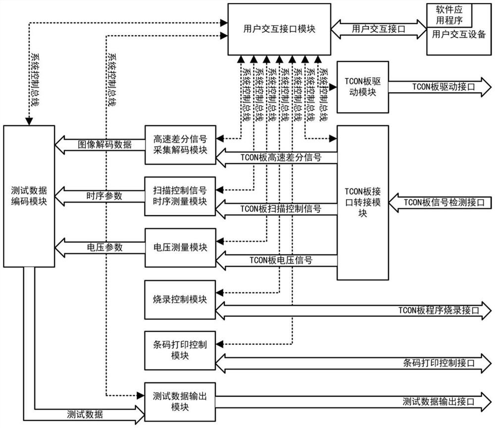
The invention provides a function test system for a TCON board and a TCONLESS mainboard. The function test system comprises a user interaction interface module, a TCON board driving module, a TCON board interface switching module, a high-speed differential signal acquisition and decoding module, a scanning control signal time sequence measurement module, a voltage measurement module, a test data encoding module and a test data output module. According to the invention, the TCON board driving module is integrated, an input excitation signal and a power supply can be provided for a to-be-testedTCON board, and a user does not need to configure a signal generator in the use process; by integrating a TCON board signal detection interface, the detection of all types of output signals of the TCON board can be completed at one time, and the function test of the TCON board can be accurately and efficiently completed.

Description

technical field [0001] The invention relates to a TCON board detection technology, in particular to a TCON board and a TCONLESS main board function test system. Background technique [0002] LCD TV is mainly composed of three parts: motherboard, TCON board and LCD screen. The motherboard obtains video data through USB, network, HDMI, AV and other interfaces, and decodes the video data into original image data, and then outputs it to the LCD TCON board through V-By-One, LVDS or eDP and other interfaces. [0003] The TCON (Timing controller) board is the sequence control board. It is used to bridge the main board and the LCD panel. It has two main functions. One is to receive the image data sent by the main board through the V-By-One, LVDS or eDP interface, and then transfer the image data to Encode according to the interface protocol requirements of the corresponding LCD screen model, and generate a synchronous LCD screen scanning control signal. Under the control of the sca...

Claims


Application Information

Patent Timeline
Patent Type & Authority Applications(China)
IPC IPC(8): H04N17/04G01R31/28
CPCH04N17/04G01R31/2881
Inventor 付慧云
Owner 广州晶序达电子科技有限公司
Learn More