Method for connecting wireless signal dead zone to achieve meter reading

A wireless signal and node technology, applied in signal transmission systems, electrical signal transmission systems, wired transmission systems, etc., can solve the problems of signal congestion, inability to apply wireless concentrators and wireless collectors, increase costs, etc., to reduce the number of transmissions and time, the effect of ensuring communication stability

Active Publication Date: 2018-04-06
ZHUHAI ZHONGHUI MICROELECTRONICS
View PDF20 Cites 11 Cited by
  • Summary
  • Abstract
  • Description
  • Claims
  • Application Information

AI Technical Summary

Problems solved by technology

[0005] The Chinese invention patent application with the publication number CN105118258A discloses a centralized meter reading networking method with dual-mode communication smart energy meters. Returned meter reading data to solve the problem of signal congestion caused by dual-mode communication of electric energy meters in the prior art
[0006] The above systems or methods can achieve the purpose of improving the success rate of meter reading to a certain extent, but must use a dual-mode concentrator and a dual-mode collector, and the dual-mode concentrator determines which channel to use to send data to achieve, but it is not applicable In the environment of existing wireless concentrators and wireless collectors, if they are all replaced with dual-mode concentrators or dual-mode collectors, it will undoubtedly increase a lot of extra costs, which is not conducive to popularization and application

Method used


Image

  • Method for connecting wireless signal dead zone to achieve meter reading
  • Method for connecting wireless signal dead zone to achieve meter reading
  • Method for connecting wireless signal dead zone to achieve meter reading

Examples


Embodiment Construction

[0026] In order to make the above and other objects, features and advantages of the present invention more apparent, the following specifically cites the embodiments of the present invention, together with the accompanying drawings, for a detailed description as follows.

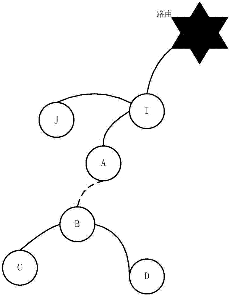
[0027] Micro-power wireless communication has been widely used in low-voltage centralized reading systems of smart grids because of its fast communication rate, high real-time performance, and not being constrained by power lines. However, micro-power wireless communication is easily affected by the use environment. When the signal is blocked, there will be a signal blind area, resulting in the failure of the signal to be transmitted. In order to solve this problem in the wireless meter reading network, the present invention proposes a meter reading method using power line carrier communication to connect nodes in wireless signal blind areas. The communication node is replaced by a dual-mode communication mo...


PUM


Abstract

The invention provides a method for connecting a wireless signal dead zone node to achieve meter reading. A micro power wireless communication node in which communication fails in a wireless signal dead zone is replaced with a double-module communication module which has an electrical line carrier communication unit and a micro power wireless communication unit, after the double-module communication module receives data, a communication channel is selected for sending the data according to different conditions, and if the data is passively returned to be sent to the node, the data is returnedto a data frame through an original path according to the channel for receiving the data; if the data is sent to other nodes in a relaying mode or actively reported, a neighbor node table is utilizedto find out the successful communication frequencies of a target node and different communication modes of the double-module communication module to determine the sending channel, and which communication channel is adopted to send the data is determined by which communication channel has the largest successful communication frequency. When the node does not exist in the neighbor table or the successful communication frequencies of different communication channels are equal, a wireless communication channel is preferentially adopted to send the data, and therefore the sending and receiving success rate is increased.

Description

technical field [0001] The invention belongs to the technical field of electric power communication, and in particular relates to a meter reading method for connecting wireless signal blind zone nodes by using power line carrier communication. Background technique [0002] Electric meter reading system is generally composed of electric energy meter, collector, concentrator, data transmission channel, and master station system. With the construction of power user information collection system of State Grid and China Southern Power Grid Corporation, the micro-power wireless communication mode has gradually become the mainstream way of concentrator downlink data collection channel due to its advantages of high communication speed, low cost, and convenient installation. one. In the process of popularizing and applying the micro-power wireless communication mode, it is found that large-scale obstructions or sealed environments can easily hinder the transmission of micro-power wi...

Claims


Application Information

Patent Timeline
Patent Type & Authority Applications(China)
IPC IPC(8): G08C17/02G08C19/00H04B3/54
CPCG08C17/02G08C19/00H04B3/542
Inventor 李宏文向铭
Owner ZHUHAI ZHONGHUI MICROELECTRONICS
Why Eureka
Try Eureka