Winding and binding technology for spiral coil of transformer

A technology of spiral coils and transformers, which is applied in the manufacture of inductors/transformers/magnets, electrical components, circuits, etc. It can solve the problems of small coil diameters, large numbers of wires, and difficult binding of wires, so as to achieve firm binding and improve coil winding. The quality of production and the effect of promoting the use

Active Publication Date: 2018-04-06
TBEA SHENYANG TRANSFORMER GRP CO LTD
View PDF5 Cites 7 Cited by
  • Summary
  • Abstract
  • Description
  • Claims
  • Application Information

AI Technical Summary

Problems solved by technology

[0002] In the prior art, the low-voltage and voltage-regulating spiral coils of AC transformers commonly have structures such as 4 helixes and 6 helixes, and the maximum will not exceed 16 helixes. However, with the development of transformer technology, the helical structure of transformer coils has broken through. The upper limit of 16 helix, for example, some products exported to the United States, the voltage regulating coil even reaches 27 helix, and in the process of winding the transformer coil of 27 helix, there are also many new problems that have not been encountered before, such as 27 helix After the spiral coil structure is wound, due to the large wire gauge of the coil wire (the wire gauge is 23 self-adhesive transposed wires), the small diameter of the coil, and the large number of wires, it is difficult to tie the wires tightly.

Method used


Image

  • Winding and binding technology for spiral coil of transformer
  • Winding and binding technology for spiral coil of transformer
  • Winding and binding technology for spiral coil of transformer

Examples


Embodiment Construction

[0022] The present invention will be described in further detail below in conjunction with the accompanying drawings.

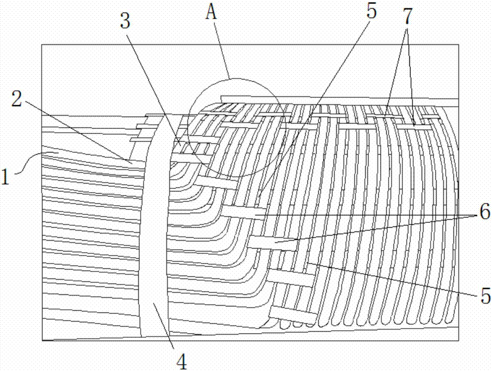
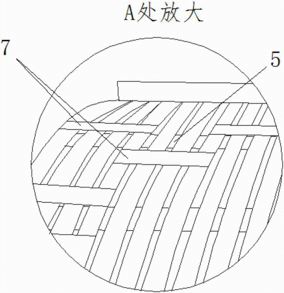
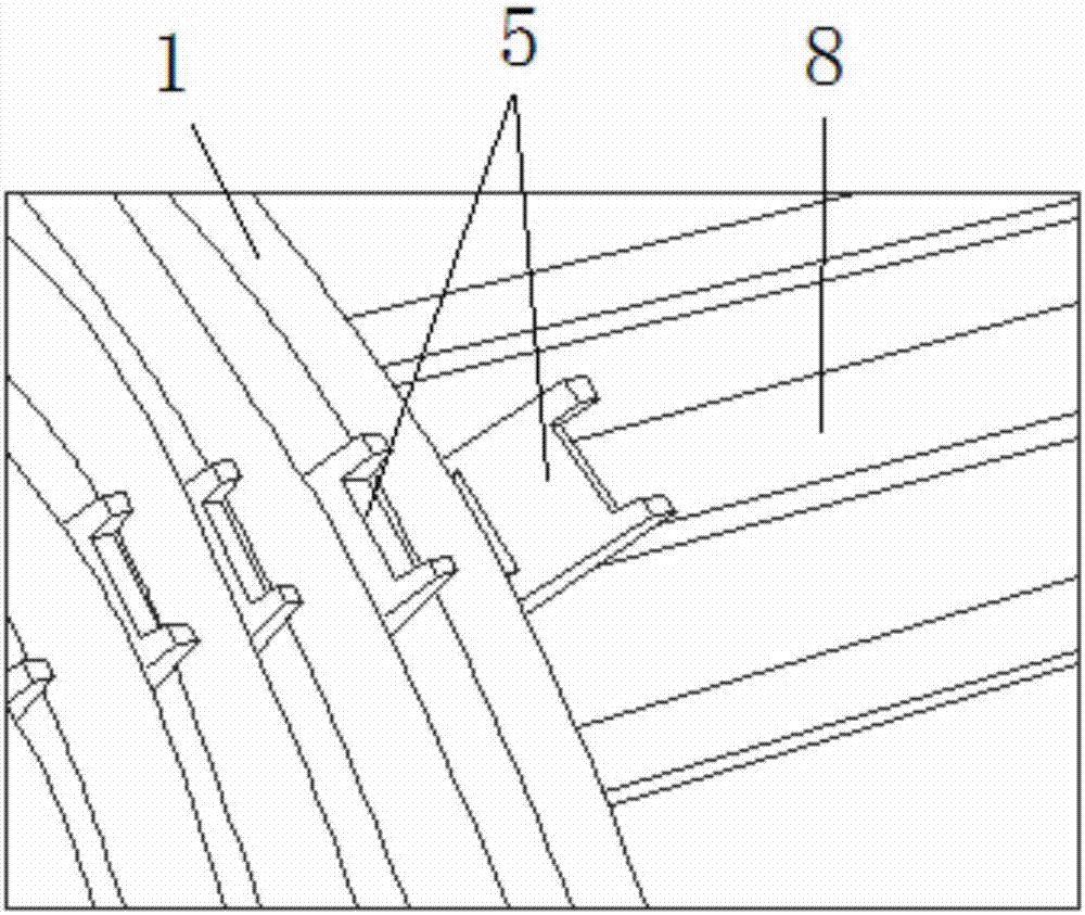
[0023] Such as Figure 1~3 As shown, the present invention includes a coil wire 1, a coil shaft, a fixing band 4 and a shrinkage band, wherein the coil wire 1 includes a wire outlet 2 and a wire body 3, and the coil shaft includes a coil winding mold shaft and a coil inner insulating cylinder, The inner insulating tube of the coil is sleeved on the shaft of the coil winding mold. The structure of the coil shaft is a well-known technology in the art. part, the wire outlet 2 is bent vertically to the same side along the axial direction of the coil axis, such as Figure 1~2 As shown, a plurality of rows of backing plates 5 are provided along the length direction of the coil shaft on the outer side of the coil inner insulating cylinder, and each backing plate 5 separates adjacent coil wires 1 respectively, as shown in FIG. image 3 As shown, a plurality of supp...


PUM


Abstract

The invention relates to the field of transformer production and manufacturing, in particular to a winding and binding technology for a spiral coil of a transformer. The technology comprises the stepsthat outlet heads of coil wires are bent into wire outlet heads; all wire outlet heads are fixed on the heads of coil winding die shafts of coil shafts through fixation bands and contraction band ropes; wire bodies of the coil wires partly wind inner coil insulation cylinders of the coil shafts; after winding is completed, the coil wires are grouped and bound through the contraction bands, wherein the connection ends, connected with the wire outlet heads, of wire bodies in all sets of coil wires, are bound through contraction bands A, the wire bodies in all sets of coil wires are partly boundthrough contraction bands B, and one or more coil wires are bound on the adjacent sides of any two adjacent sets of coil wires by the adjacent contraction bands which belong to different coil wire sets respectively; after the wire outlet heads are bound, the contraction band ropes and the fixation bands are disassembled. According to the winding and binding technology, it can be guaranteed that multi-spiral coil outlet heads are firmly bound, and the winding quality of the coils is improved.

Description

technical field [0001] The invention relates to the field of transformer manufacturing, in particular to a winding and binding process of a transformer spiral coil. Background technique [0002] In the prior art, the low-voltage and voltage-regulating spiral coils of AC transformers commonly have structures such as 4 helixes and 6 helixes, and the maximum will not exceed 16 helixes. However, with the development of transformer technology, the helical structure of transformer coils has broken through. The upper limit of 16 helix, for example, some products exported to the United States, the voltage regulating coil even reaches 27 helix, and in the process of winding the transformer coil of 27 helix, there are also many new problems that have not been encountered before, such as 27 helix After the helical coil structure is wound, it is difficult to tie the wire at the end because of the large gauge of the coil wire (the wire gauge is 23 self-adhesive transposed wires), the sma...

Claims


Application Information

Patent Timeline
Patent Type & Authority Applications(China)
IPC IPC(8): H01F41/066H01F41/082
Inventor 刘静马秀峰
Owner TBEA SHENYANG TRANSFORMER GRP CO LTD
Why Eureka
Try Eureka