Mold special for wire harness winding, winding device and lamp manufacturing process

A winding device and winding technology, which is applied to lighting devices, lighting device parts, transportation and packaging, etc., can solve problems such as low production efficiency, inconsistent spacing between illuminants, and increase production costs, and achieve strict inspection processes. The effect of improving wire harness winding quality and welding quality

Active Publication Date: 2016-11-16
TAIZHOU WANLI LIGHTING MFG CO LTD
View PDF7 Cites 11 Cited by
  • Summary
  • Abstract
  • Description
  • Claims
  • Application Information

AI Technical Summary

Problems solved by technology

[0004] As we all know, the overall length of the above-mentioned type of holiday light strings is relatively long, and a long string line is required to weld such a length of holiday light strings. Traditional processing workshops do not arrange placement boards of such length, so operators are required to For segmental welding, the operation steps are cumbersome and the production efficiency is low. Some manufacturers use the attached figure 1 The wire harness winding mold shown in , which includes a main template 1, a secondary template 2 connected to the main and secondary templates, and the outer wall of the secondary template 2 is provided with a number of embedding grooves 3 distributed along a straight line, and the adjacent embedding grooves 3 The spacing between them is kept consistent. In the actual use process, the operator winds the series wires on the main formwork 1 and the auxiliary formwork 2, and each time the series wires are wound around, the series wires and the embedding grooves 3 are set in one-to-one correspondence. Then the operator welds a luminous body on each serial line in turn
[0005] For different batches of holiday light strings, the spacing of the illuminants is inconsistent. At this time, the manufacturer needs to prepare different types of wire harness winding molds for different batches of holiday light strings, which greatly increases the production cost.

Method used


Image

  • Mold special for wire harness winding, winding device and lamp manufacturing process
  • Mold special for wire harness winding, winding device and lamp manufacturing process
  • Mold special for wire harness winding, winding device and lamp manufacturing process

Examples


Embodiment 1

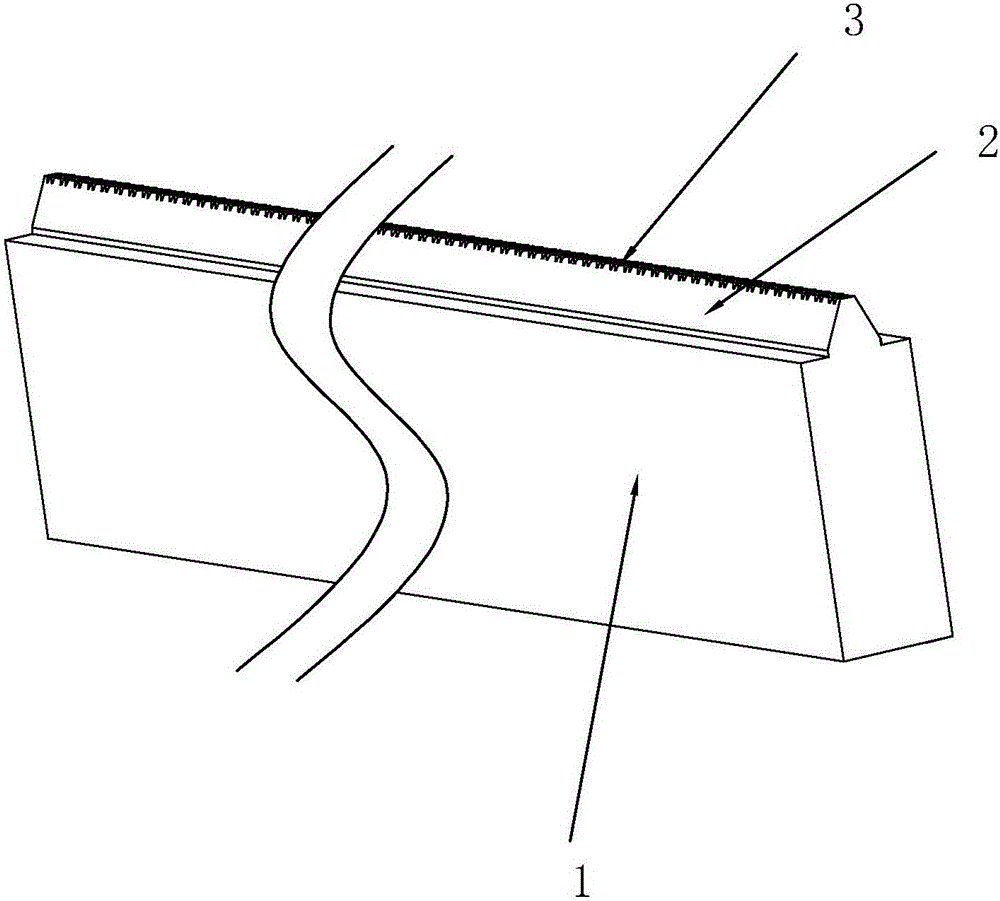
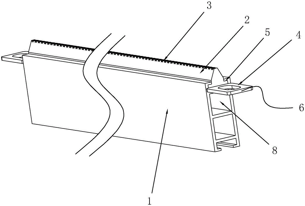
[0070] see figure 2 As shown, a special mold for wire harness winding includes a rectangular main template 1, a sliding groove 5 is provided on an outer wall of the main template 1, and the cross section of the sliding groove 5 is T-shaped, and the sliding groove 5 The length direction of the main template 1 is consistent with the overall length direction of the main template 1; it also includes a secondary template 2, which can be adapted to the sliding groove 5, and can realize sliding movement along the length direction of the sliding groove 5. On the side wall of the sub-formwork 2 away from the bottom of the sliding groove 5, there are a number of embedding grooves 3 distributed along a straight line, and the intervals between adjacent embedding grooves 3 are kept consistent;

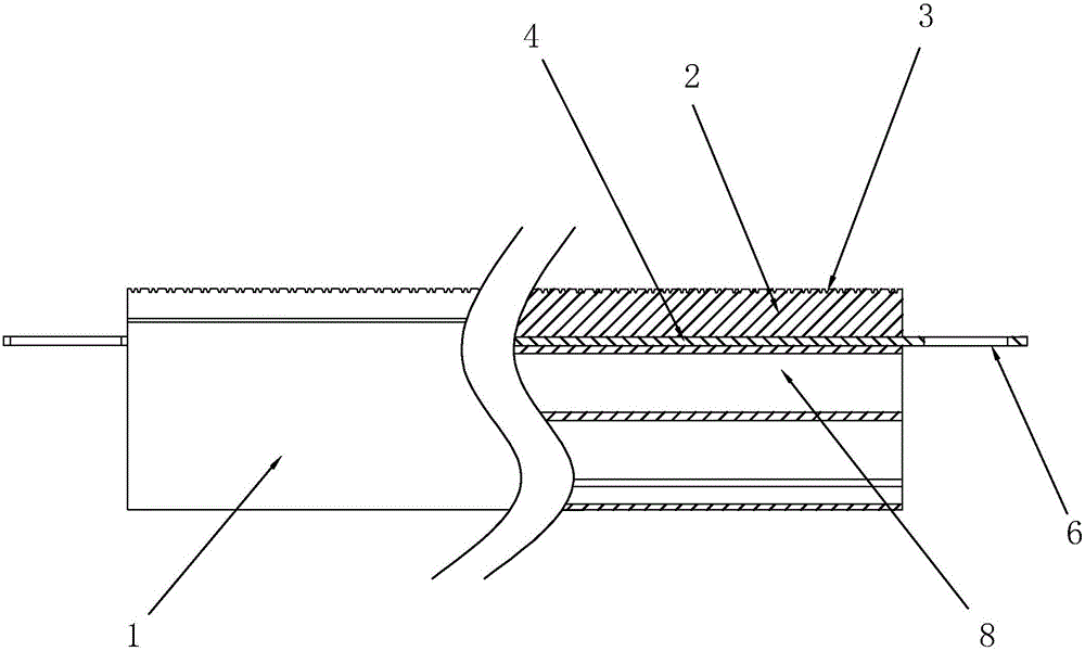
[0071] Also, see figure 2 as well as image 3 As shown, between the sub-formwork 2 and the bottom of the sliding groove 5, a plug-in board 4 is inserted, and the shape of the plug-in board 4 is...

Embodiment 2

[0076] see Figure 4 as well as Figure 7 As shown, a winding device includes a frame 35, on which a special wire harness winding die, a traction mechanism 19, a first pressing part 9, and a second pressing part 12 are arranged on the frame 35; A pressing part 9 includes a cylindrical first pressing head 10 and a first driving assembly 11, the first driving assembly 11 may be an optional drive motor and the first driving assembly 11 is used to drive the first pressing head 10 to rotate in a circumferential direction ; The second pressing part 12 includes a second pressing head 13 coaxially arranged with the first pressing head 10, and a second driving assembly 14, and the second driving assembly 14 is used to drive the second pressing head 13 to approach or move away from The first pressing head 10 moves in the direction, the second pressing head 13 is rotatably connected to the second driving assembly 14, and the two ends of the wire harness winding die are respectively pres...

Embodiment 3

[0089] A lamp manufacturing process, comprising the following steps:

[0090] Step 1. Winding: Use the above-mentioned winding device to wind the series wires on the special mold for wire harness winding, in which it is required that each wire embedding groove 3 should be embedded with a series wire;

[0091] Step 2. Adhesive tape: Attach the tape along the length direction of the main template 1 to the wire harness winding mold with the serial wire wound in step 1. After the string wire winding is completed, the wire harness winding mold will display Spiral distribution, relying on the adhesive force of the tape, so that there will be no deformation between the spiral distribution series wires wound on the same wire bundle winding special mold;

[0092] Step 3. Grinding of serial wires: Use an abrasive belt grinder to grind the serial wires on the wire harness winding mold in step 2, and remove the outer insulating varnish of the serial wires located in the embedding groove 3...


PUM


Abstract

The invention discloses a mold special for wire harness winding, a winding device and a lamp manufacturing process. According to the technical scheme, the mold special for wire harness winding comprises a main mold plate and an auxiliary mold plate; the outer plate wall of the auxiliary mold plate is provided with a plurality of inserting line grooves distributed along a straight line; and the distance between the adjacent inserting line grooves is kept to be consistent; the mold special for wire harness winding further comprises inserting-connection plates; the main mold plate is provided with a slide groove, and the auxiliary mold plate is slidably arranged in the slide groove; the edge of the auxiliary mold plate with the inserting line grooves is protruded out of the main mold plate; and the production cost of the mold special for wire harness winding can be substantially reduced; the winding device has the characteristic of being capable of enabling a tandem connection wire to be efficiently wound on the mold special for wire harness winding; and the lamp manufacturing process can improve the lamp manufacturing quality.

Description

technical field [0001] The invention relates to the technical field of lamp manufacturing, in particular to a special mold for wire harness winding, a winding device and a lamp manufacturing process. Background technique [0002] Holiday lights have been widely used as a kind of lamps and lanterns for beautifying the environment, facade decoration, and adding festive atmosphere. Existing festival lights such as the Chinese utility model self-illuminating festival light string whose announcement number is CN204693312U include one or more A serial line connected in various forms. There are multiple illuminants on the series line. The above-mentioned type of festival light string only needs a single point of power supply, and the illuminants on the same series line can be lit at the same time. Its use It is very convenient, and the shape can be changed at will according to the actual use situation, which is well received by the market. [0003] For the above-mentioned types of...

Claims


Application Information

Patent Timeline
Patent Type & Authority Applications(China)
IPC IPC(8): B65H75/10B65H75/22B65H54/02B65H57/28B65H57/14F21V19/00
CPCB65H54/02B65H57/14B65H57/28B65H75/10B65H75/22F21V19/00
Inventor 赵崇祥
Owner TAIZHOU WANLI LIGHTING MFG CO LTD
Why Eureka
Try Eureka