Electric vehicle battery box housing having heat dissipation and water exhaust structure

A technology of electric vehicle battery and drainage structure, which is applied in the direction of secondary battery, structural parts, battery pack parts, etc., and can solve the problems of losing the weight of the battery box, reducing the volume and reducing the number of batteries, etc.

Active Publication Date: 2018-04-06
METAL INDS RES & DEV CENT
View PDF9 Cites 12 Cited by
  • Summary
  • Abstract
  • Description
  • Claims
  • Application Information

AI Technical Summary

Problems solved by technology

The main items to be overcome in the domestic development of lightweight battery box shells are: 1. The structural strength (rigidity requirements) of the shell: the battery box shell is mounted on the vehicle and must comply with the vehicle body collision safety design; 2. Heat dissipation / flow path Design (life) issues: The temperature control of the battery box shell will determine the service life of the battery core; 3. Lightweight / manufacturability (improvement) issues: The lightweight design of the battery improves the weight energy density and increases endurance; 4. Fatigue / Waterproof (regulations) issues: the shell must meet functional requirements such as long-term use (fatigue) and wading (waterproof)
However, each battery of this patent is covered with a frame, and a large gap for gas to pass is reserved between each frame, so the battery box of this patent can be assembled under the same volume. It must be greatly reduced, losing the meaning of the weight and volume of the battery box

Method used


Image

  • Electric vehicle battery box housing having heat dissipation and water exhaust structure
  • Electric vehicle battery box housing having heat dissipation and water exhaust structure
  • Electric vehicle battery box housing having heat dissipation and water exhaust structure

Examples


Embodiment Construction

[0062] The present invention will be further described below in conjunction with the accompanying drawings and specific embodiments, so that those skilled in the art can better understand the present invention and implement it, but the examples given are not intended to limit the present invention.

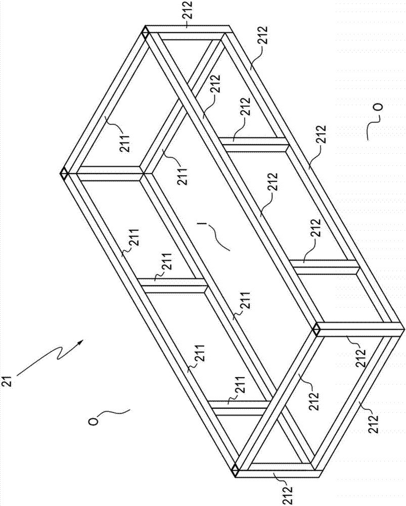
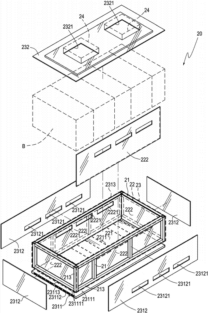
[0063] Please refer to Figure 2 ~ Figure 4 shown. The electric vehicle battery case housing with heat dissipation and drainage structure in this embodiment is mainly suitable for accommodating a battery module B. The electric vehicle battery case housing 20 includes a frame 21, an inner box body 22 and an outer box Body 23: The frame 21 has an inner surface 211 facing the inner I of the frame 21 and an outer surface 212 facing the outer O of the frame 21. In one embodiment, the frame 21 is made of a plurality of extruded aluminum The bracket 213 is assembled; the inner box body 22 includes an inner bottom plate 221 joined to the bottom surface of the inner surface 211 and a plur...


PUM


Abstract

The invention discloses an electric vehicle battery box housing having a heat dissipation and water exhaust structure and is suitable for an electric vehicle and used for accommodating a battery module. The electric vehicle battery box housing includes a frame, an inner layer box, an outer layer and a heat dissipation board. The frame includes an inner surface and an outer surface. The inner layerbox is connected to the inner surface of the frame with a plurality face boards and a box-shaped accommodation space is formed for accommodating the battery module. The inner side board of the box-shaped accommodation space is provided with high-position through holes. The outer layer box body is connected to the outer surface of the frame with a plurality of face boards and a box-shaped body isformed. The outer bottom board is provided with a plurality of penetrating water exhaust holes. The outer side board is provided with low-position through holes corresponding to the high-position through holes. The cover body is provided with penetrating air vent holes. The heat dissipation board is disposed below the outer bottom board of the outer layer box body. The heat dissipation board is provided with a water exhaust and venting channel corresponding to the water exhaust arranging zone of the outer bottom board.

Description

technical field [0001] The present invention relates to a battery box shell of an electric vehicle, in particular to a battery box shell provided on an electric vehicle to accommodate battery components and has a heat dissipation and drainage structure. Background technique [0002] Global oil prices are rising, environmental protection awareness is rising, and the development of the electric vehicle industry has become the focus of global attention. Among them, lightweight issues have attracted the most attention. In particular, the development trend of electric vehicle battery module shell technology will be lightweight, fast manufacturing, easy integration and safety. sexual development. The main items to be overcome in the domestic development of lightweight battery box shells are: 1. The structural strength (rigidity requirements) of the shell: the battery box shell is mounted on the vehicle and must comply with the vehicle body collision safety design; 2. Heat dissipat...

Claims


Application Information

Patent Timeline
Patent Type & Authority Applications(China)
IPC IPC(8): H01M2/10H01M10/613H01M10/625H01M10/6563H01M50/20
CPCH01M10/613H01M10/625H01M10/6563H01M50/20Y02E60/10
Inventor 林典永成庭皓
Owner METAL INDS RES & DEV CENT
Why Eureka
Try Eureka