Eureka AIR delivers breakthrough ideas for toughest innovation challenges, trusted by R&D personnel around the world.

Silicone coating cloth and air bag

A technology of coating silicon and silicone, applied in the direction of pedestrian/occupant safety arrangement, textile, fabric, etc.

Inactive Publication Date: 2004-08-04
ASAHI KASEI KK
View PDF8 Cites 13 Cited by
  • Summary
  • Abstract
  • Description
  • Claims
  • Application Information

AI Technical Summary

Problems solved by technology

However, there is no description of the design of the coated cloth that can reduce the weight of the airbag and maintain the pressure

Method used

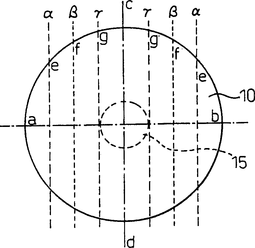
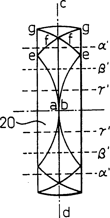
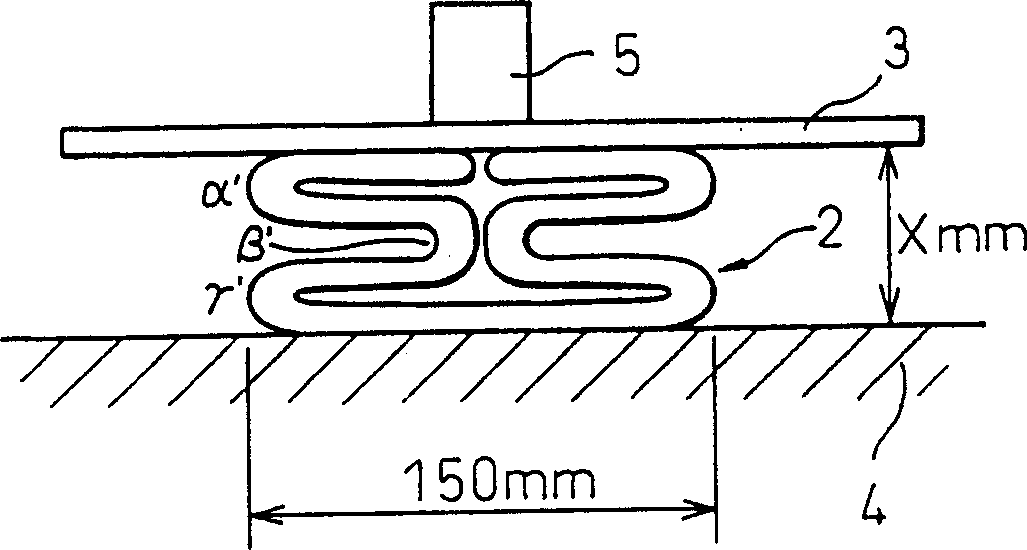

Image

  • Silicone coating cloth and air bag
  • Silicone coating cloth and air bag
  • Silicone coating cloth and air bag

Examples


Embodiment 11~13 and comparative example 11~12

[0119] Nylon 66 as described in Japanese Patent Application No. 2001-050177 was melt spun with an extruder type (Extruder one) spinning machine, and after the spinning oil was attached, thermal drawing was carried out to obtain nylon yarns of various finenesses. The yarn had a tensile strength of 8.5 cN / dtex, a degree of elongation of 21%, and an oil agent adhesion amount of 1.0% by weight.

[0120] Spinning oil is added by nozzle oil injection method, as "dialkyl thiodipropionate (dialkyl thiodipropionate) 40 parts, PO / EO alkyl polyether 30 parts, POE hardened castor oil trialkyl 30 wt% hydrocarbon solution of 30 parts of ester.

[0121] When warping the yarn, add 1.0% by weight of warping oil by means of an oil supply roller, its trade name is "S1700" (manufactured by Huo Chemical Industry Co., Ltd.), and prepare warp yarns such as bundling, so that the warp yarn raw The total amount of oil attached to the silk was 2.0% by weight, and each fabric was produced by an air jet ...

Embodiment 21~27 and comparative example 31~38

[0130] The same coated cloth as in Example 11 was prepared and evaluated for tensile strength and tear strength. Tables 2 and 3 show the results.

[0131] Table 2

[0132] Example 21

Example 22

Example 23

Example 24

Example 25

Example 26

Example 27

through

latitude

through

latitude

through

latitude

through

latitude

through

latitude

through

latitude

through

latitude

Total fineness (dtex)

115

115

155

155

155

155

235

235

235

235

235

235

235

235

Monofilament fineness (dtex / filament)

3.2

3.2

3.2

3.2

3.2

3.2

3.2

3.2

3.2

3.2

3.2

3.2

2.9

2.9

Base fabric unit weight (g / m 2 )

107

106

121

117

147

128

147

Total coating weight (g / m 2 )

...

Embodiment 41~43 and comparative example 41~43

[0138] The same coated cloth as in Example 11 was prepared and evaluated. The fiber fineness and fabric composition used were changed, and the biaxial tensile test was carried out. The results are shown in Table 4.

[0139] Table 4

[0140] Example 41

Example 42

Example 43

Example 43

Comparative Example 41

Comparative Example 42

Comparative Example 43

through

latitude

through

latitude

through

latitude

through

latitude

through

latitude

through

latitude

through

latitude

Total fineness (dtex)

115

115

155

155

235

235

235

235

78

78

470

470

940

940

Monofilament fineness (dtex)

3.2

3.2

3.2

3.2

2.9

2.9

2.9

2.9

3.2

3.2

6.7

6.7

6.7

6.7

Fabric Stren...


PUM


Abstract

The present invention provides a silicone coated fabric comprising a base woven fabric that is formed from a synthetic fiber weaving yarn that has a yarn size of from 100 to 270 dtex, and a weaving size expressed by a product calculated by multiplying the yarn size of a weaving yarn and a weave density (ends or picks / 2.54 cm) of from 10,000 to 25,000 (dtex.ends (or picks) / 2.54 cm) in both the warp direction and the weft direction, a silicone being applied to the woven fabric in an amount of from 5 to 25 g / m<2>, and having on one side a uniform silicone coating layer formeding part of the silicone mentioned above. The silicone coated fabric of the present invention is a lightweight coated fabric that shows improved heat resistance, improved flexibility and an improved low coefficient of friction as well as particularly improved burning resistance. The fabric can therefore be used for producing lightweight and compactly storable airbags that suppress bursting starting from a burnt-through-hole, and that shorten a deployment time.

Description

technical field [0001] The present invention relates to a light and soft silicone-coated cloth with good flame resistance and mechanical properties, a method for producing the same, and an airbag composed of the above-mentioned cloth. Background technique [0002] The airbags that are installed to ensure the safety of passengers when the car collides are usually installed in narrow places such as the steering wheel and instrument panel of the car in the form of a built-in booster pump and airbags. Recently, side airbags and side curtain airbags have been installed in automobiles in response to collisions from the side of the automobile. However, these changes are also stored in narrow places such as the sides of car seats and roof pillars. Under such circumstances, in order to ensure a large living space in the vehicle, it is required to reduce the storage volume of the airbag as much as possible and to reduce the weight of the airbag device. [0003] In order to meet such ...

Claims


Application Information

Patent Timeline
Patent Type & Authority Applications(China)
IPC IPC(8): B60R21/16B60R21/235D03D1/02D06N3/00D06N3/12
CPCB60R2021/23514B60R21/235D03D1/02D06N3/0002D06N3/128Y10T428/1321Y10T428/1314Y10T428/1307Y10T442/2139Y10T442/2803Y10T442/20Y10T442/3179Y10T442/3301Y10T442/322D06M15/643
Inventor 石井秀明长冈利郎
Owner ASAHI KASEI KK
Why Eureka
Eureka Blog
Learn More